|
|
| "Tweakings" (Part
2) Thoughts about diy collimation of a compound microscope By Paul James |
Part 1 here.
I'm not sure whether my experiences in microscopy are unique regarding misaligned optics, but I do seem to have inherited the knack of acquiring a stand which isn't quite 'tuned'. Either the binocular head is slightly askew, or the lamphouse/condenser assembly isn't generating a properly centered field etc. etc.. The list is extensive all told, varying from the obvious to the more subtle of ailments. Rectifying these 'blemishes' can vary in difficulty ranging from a simple screwdriver tweaking, to the extremes of having to make use of the engineer's lathe. The one single virtue of all this is that I have become much more aware of how to get the best from a microscope....but achieving it however can still be a problem with an abused stand or a mass produced student instrument. Those stands that have been cobbled together or indeed broken up for parts for eBay sales serve only to increase the number of misaligned 'scopes in circulation.
The prime purpose of this article is to hopefully help the owner of a compound microscope which is found wanting of adjustments to identify the inherent problem(s). The next step, that of correcting these error(s) I leave to the discretion of the owner. The permutations arising from the range of 'scopes out there and the various problems encountered from misalignments are so vast that I cannot begin to contemplate any advice regarding the 'cures'. However one or two of the tricks required for successful 'tweaking' stem directly from understanding the basics.......
These notes therefore, might hopefully help those who have found some asymmetry in their microscope's imaging to hone their 'scope into better collimation. I say better, simply because this is a more realistic goal to pursue than to aim for perfection, which is much more likely to be imagined than realised, for there is no such thing as a perfectly collimated microscope : they simply range from the good, the adequate to the very poor examples.
|
|
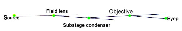
The diagram above is somewhat exagerrated but shows in the simplest diagramatical sense the deviation of light through a very poorly collimated 'scope..... the sort of situation I've found too often. The object of our endeavours is to straighten the kinks out, or at least reduce these errors.
A Simple Premise
|
|
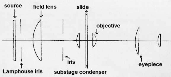
A well collimated or aligned compound microscope will have all its optical components, mirrors, substage lamphouses optics, condensers, objectives, tube lenses, prisms and eyepieces etc., coincident with the stand's designed optical/mechanical axis. Such a well adjusted stand will issue a single ray of light from dead centre light source through to the dead centre of the last lens of the eyepiece after having passed through all the glassware in the interior, without deviation. The next step in our approach to the practical application of a cure, is to think about the housing of all this glassware, because theoretically all the lenses should be accurately mated in both centration and yaw with their respective mountings. By that it is meant that the dead central optical zone of all the lenses etc. coincides with the mechanical centre of the mounts, and that the optical surfaces are themselves at right angles to this axis, that is they are free from 'yaw'. Prisms all have an optical axis too, but their mounting is complex, and though some can be fine tuned many are fixed or cemented in place. Fortunately the higher quality 'scopes usually have adjustments to centralise most if not all these optical components.
Preparations
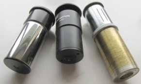
In order to do this effectively and with efficiency a phase telescope with a focussing eyepiece is a must, though some indication of the state of collimation of the optical mounts can be ascertained by direct visual observation, but this relies heavily on experience.
|
|
Ideally a phase 'scope with a focussing range between infinity and about 4" will be an immeasurable aid enabling all optical surfaces to be scrutinised as well as their axial centrality. Watchmaker's screwdrivers are a must as well as hand tools of course.
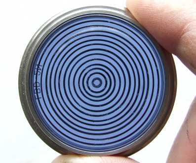
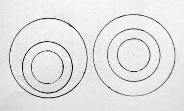
In addition to the foregoing items, a simply devised centering 'tell tale' can be made by marking a glass filter with concentric circles which will fit over your field len's mounting. It has the benefit of transmitting the light from the source whilst displaying the rings simultaneously. The rings should be less than 2mm apart to be of practical use, though the consistency of their spacing is not important at all, but their concentricity is most essential. The one illustrated below was fashioned on a turntable using a felt tipped pen on a glass filter.
|
|
This indispensible aid can be brought into play at any given moment to suit the particular test. Its purpose is to make easier comparison between widely spaced field edges which you'll see through the phase telescope during inspection, without blocking too much light from the interior parts. The whole point of this telltale is to bridge the gap between two interior circles with its own concentric rings, making comparisons much easier and more accurate. I'll not mention this tell tale again, assuming that its use to be rather obvious as you proceed through the stages of inspection. Both the stand's base unit and the stage, can be useful planes to support it during use.
|
|
Detecting misaligned optics left by recognition of asymmetry |
Starting the simple way
Anyone who has never considered their own testing might be surprised at how easy some of the alignment checks can be.
The very first thing to do is to ascertain the accuracy of the eyepiece's mounting....ie whether the mechanical tube in which it is housed actually points towards dead centre light source, and is therefore coincident with the optical axis. This is very important because any deviation here cannot be easily rectified. An eyepiece tube which is found to be offset will be a rare occurence indeed, but this still needs to be tested at the outset. Binocular heads are however prone to misalignment, and they can be difficult to correct accurately, unlike the eyepiece tubes of monoculars which are inherently stable.
1) Lamphouse source / Eyepiece
Remove the field lens, substage condenser, and one objective from its turret, then observe the internal situation with the phase telescope focussed on the light source. Hopefully everything looks symmetrical : that is the periphery of the source coincides perfectly with other circles generated by the interior walls of the mechanical mountings in that region. Very importantly the lamphouse iris diaphragm should be in very close concentricity within the field of view and appear to match the outer circles seen around the source*. So without any intervening optics we can estimate/establish the accuracy of the eyepiece's alignment towards the light source, and its iris.
* It is assumed that both the lamphouse optics and iris are both coincident.
I think it prudent, though you might possibly feel I'm being a little too pernickity, to actually test the eyepiece's own optical alignment within its housing. Since it is a very simple exercise, and given that some eyepieces are surprisingly out of kilter, I think it is important to find out.
The test is simple : Place the eyepiece back in its seating and observe a slide of dispersed moth scales or the like using any objective in BF. Rotate the eyepiece evenly through 360 degrees whilst being conscious of the edge of a one part of the field of view. Theoretically the specimen scales and field edge should remain stationary, but more than likely there will be some variation between the two. This condition is not as uncommon as you might expect, and can in some circumstances be a virtue in slightly misligned binocular heads........but more of that for a later article.
2) Lamphouse / Objective mount / Eyepiece
Now we come to the more difficult part which requires ideally an insert with the same RMS thread of an objective, which has an inbuilt concentric hole of about 4-5 mm diameter. The idea is to reduce the opening at this objective plane so we can again compare this with the ever increasing layers of lamphouse iris/field boundaries made apparent with the phase 'scope.
|
|
|
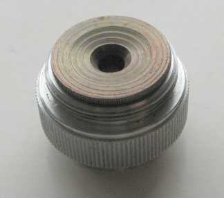
Any redundant objective with lens removed but leaving rear aperture stop in place is ideal. |
If you have an old redundant objective which is beyond usability, it can be taken apart leaving any of the stops inplace, but without any glass left inside. These stops are usually only a few millimetres across and serve our purpose perfectly.
When this stop is screwed into any one of the apertures in the objective turret, it will show as a circular field similar to the others, and by focussing on this with the phase telescope, or partial focussing between field edges you will become familiar with their respective placement as you view progressively from one plane to the next. So now we have both source iris and objective centrality comparisons. Opening or closing down the light source iris may be needed to illuminate the view to best advantage. Theoretically the circles viewed should be near perfectly concentric. Check other objective apertures in the objective turret to satisfy yourself that they too are similarly concentric. It is quite likely that there will be some slight discrepancies throughout. No matter since you can make a note of the most accurate one and reserve this in future for the x 40 objective, as this and the x100 need to have the best illumination accuracy.
3) Lamphouse / Substage condenser / Objective mount / Eyepiece
Now repeat the inspection process by installing the substage condenser. If the appearance through the phase 'scope indicates fair concentricity, place your x40 objective in the turret and bring the objective into its normal position above the stage as if focussed on a slide. Examine the back lens of the objective where you will find a diminished but more critical image of the state of internal alignment. Close down alternately the substage and lamphouse condenser iris's to gauge the concentricity of both. You will soon familiarise yourself with each of the 'circles' and which plane they represent, as by extending the length of the phase telescope brings into focus ever higher planes. If you have an Abbe condenser its adjustment above and below its normal position, will generate colourful circular zones within the backlens. If your condenser is found out of true and is one with no lateral adjustments, then clearly you will have to alter the mount in order correct this.
4) Lamphouse / Field Len s/ Substage condenser / Objective mount
Lastly the field lens can now be placed in position to see if its mount in the base coincides with the optical pathway. Don't be too surprised if this doesn't work out as expected. This is the part of the whole operation when an important decision may have to be made, because the mechanical latitude of any adjustments that may be present in this region might seem inadequate, and cannot bring about a successful centering of the field lens. The real problem if it exists is that the source's centre is dictated by its own iris diaphragm, which is usually fixed in place. Those 'scopes having no iris's at their source have no problems with the field len's citing accuracy simply because the source is usually wide enough to allow for assembly line variations. Wild's M20's field lens, which is user adjustable certainly helps smooth out the small inherent variations of objective parcentricity. Widening a field lens's mounting hole might ultimately be a worthwhile proposition............?
Odds and Ends
Having only covered the very basics above, you might find your 'scope is a little more complex.....maybe an internal limb tube lens corrector or field flattening lens exists above the turret for instance. I expect that the centrality of these internal correction devices to be inherently accurate and since they are basically out of reach from twiddlers they can be left undisturbed. Their effect on the internal inspection process causes the phase telescope's imagery to be a little smaller than normal. If they can be removed by pulling out of their socket....fine, but if they are well screwed down, leave them.
Concluding thoughts
I've skipped through the basics of diy inspection process of assessing the inner state of the optics of a compound microscope hoping that familiarity with the method will bring about a better understanding of what counts regarding adjustments. Thus the revelations of peering through the phase telescope coupled with some carefully thought out logical steps of how to go about adjusting one or more of the components back into alignment, should do the trick, but haste in this endeavour to improve matters can easily cause a worsening of alignment, so it pays to think very carefully before proceeding with the tools.
You can be sure, that when the internal views throughout your 'scope look perfectly symmetrical through the phase telescope. ....all the ring edges and even any circular reflections appear wholly concentric, your job of diy collimating has been successful.
| All comments welcome by the author Paul James |
Microscopy UK Front Page
Micscape
Magazine
Article
Library
Please report any Web problems or offer general comments to the Micscape Editor.
Micscape is the on-line monthly
magazine of the Microscopy UK web
site at
Microscopy-UK