It occurred to me recently that Ive always accepted the markings on my objective lenses on faith and have assumed, for example, that 100x really did present an image ten times 10x, or 2.5 times 40x. I use a set of standard A/O plan achro lenses: 10, 20, 40 and 100. In order to test the lens accuracy, I measured the width of my ocular field with each lens by using a micrometer head to determine how far the x-stage had traveled when a tiny dust speck moved across the field. A micrometer stage slide will also do the job, though somewhat less precisely.
The results offered no particular surprise: My field widths were 1.920 mm, 0.961 mm, 0.488 mm and 0.187 mm for the respective lenses listed. My 100x lens, therefore, presents an image that is 10.27 times as large as my 10x lens. To the extent that a standard reticle scale is printed in actual size units, it doesnt accommodate the differences in my lenses an object that measures 150 microns at 40x will measure over 156 microns at 100x. Clearly, this isnt a fatal flaw for most of us however, the fellow who measures particles for a living usually expects a bit more accuracy, and applies a set of calibration factors to his lenses.
As an amateur, my measurement curiosity usually only arises at 100x, and I was reluctant to pay $60 for a good reticle in any case, so I decided to simply print one for casual use. The attached digital reticle is a CAD drawing of a simple 20-division scale, scanned at a considerable reduction the resulting 230KB file is full of resolution at any reduced size, and can be resized to accommodate lens inaccuracy or uneven lens powers, then printed on a transparency sheet.
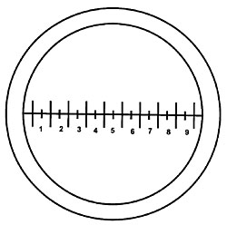
Click image to download master
image in tif format.Resizing is a fairly simple two-print process: Measure the inner diameter of your eyepiece field stop, where the reticle rests lets assume it measures about 19.3 mm. Print out the attached file onto a transparency sheet (the inner circle is 20 mm wide) and cut out the reticle so that it fits symmetrically into your eyepiece. If your field stop ID is over 20 mm, resize the drawing first so that the inner circle is slightly larger. With this temporary reticle in your eyepiece, count the number of divisions within your full field of view, 19.5 for example. Next, measure your field of view accurately, as illustrated above lets assume you have a 100x lens with my field size, i.e., 0.187 mm. You want the final scale to show 18.7 divisions within this field, so digitally enlarge the image by 19.5/18.7 = 1.043. Reprint, cut out and insert the final reticle. Now, any object under this lens that fully fills one minor division is exactly 10 microns in size.
I use Microsofts Photo Editor to resize the drawing it allows you to specify pixels as units of measurement, so enlargements or reductions are reasonably precise. For best results, print using a decent quality laser printer, 600 dpi or better play with the print density to minimize scattered toner. As you might expect, the optical quality is something of a disaster under a 10x eyepiece, compared with a commercial reticle. You can see through it clearly, however, and it does its job very well, given the printing method and materials employed.
Measuring field width accurately requires a precision instrument and careful technique micrometer stage slides cost $50 and up, and generally read out in 10-micron divisions, at that price. Micrometer heads are somewhat less expensive, and a bit more precise I found a new one on Ebay for $11, including postage, that reads out to 1 micron, then made a fairly crude clamp using a piece of oak scrap to hold it in place tightly at the end of my stage slide (see picture). In practice, measurements down to 1 micron arent very realistic using manual techniques, but you can come fairly close. Using this kind of setup, you can expect repeatable measurements at 100x within 2 or 3 microns. At that level, you are operating close to the stated accuracy of the instrument about 2 microns. Your measurement result should account for lens resolution, instrument accuracy and any known uncertainty at 10x, for example, if I can resolve and work with a 7-micron speck, then my field size is 1920 ±9 microns. At 100x, with resolution under 0.5µ, Im comfortable with an error rate at ±3µ in my 187µ field this translates to a calculated measurement error of 160 nanometer for a 10-micron object, well below the limit of resolution.
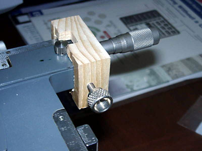
Micrometer head attached to mechanical stage.Of course, you can just forego the measurement process and simply use the reticle at actual size with no compensation for your lens: An object that occupies four minor divisions (4 mm) under a 10x lens is about 400 microns wide. Perhaps youll wonder, though, if it isnt really 430 microns?
Contribution by Larry Jenkins, comments welcomed.Editor's note: Related Micscape articles.
For an overview of measurement techniques for the microscope, see Walter Dioni's article About microns, measurements and meters.