LED Illumination For Microscopes.
Fed up with filament bulbs going 'pop' and a drawer full of filters? .... Have a go at building your own LED microscope illuminator with a simple battery supply which lasts hours!
By Ian Walker. UK.
Introduction .
LEDs or Light Emitting Diodes are semiconductor devices capable of generating light when a voltage is applied to their terminals; this phenomena is called electroluminescence. Unlike the filament bulb which generates much heat these diodes provide a cold light source and depending on which semiconductor material is used can generate different colours of light. Gallium arsenide [GaAs] generates light in the infra-red region, gallium phosphide [GaP] generates red light when **doped with oxygen or green light when doped with nitrogen, other dopants in various amounts can create other colours of the light spectrum. LED lamps come in all shapes and sizes from tiny ones barely bigger than a pin head to giant LED arrays capable of lighting up road signs and shop displays. Here we are concerned with modest single LEDs of about 5mm diameter. Thirty years ago you would probably be limited to seeing dull red or green units of about 3mm diameter which were used extensively in consumer products like hi-fi's and video recorders etc. Now the full range of colours are available within the whole visible spectrum plus ultra-violet [typically used in forensics] and infra-red emitters found in your remote control hand sets. Some of the major manufacturers of specialist LEDs include Hewlett Packard, Kingbright and Nichia, it is one of Nichia's LEDs I have used for my final light assembly.
** dopants is a term given to 'impurities' added to the semiconductor material to provide the requisite colour or emitter characteristics.
What are 'white' LEDs?
White LEDs are made by adding special phosphors to blue LEDs, we can thank Shuji Nakamura for inventing the blue LED and a fascinating account of his work on blue laser diodes and LEDs can be found on the S CIENCE W ATCH website.
Advantages & disadvantages of using LED in microscope illuminators over filament bulbs.
Main advantages over filament bulbs:
Extremely efficient lighting only requiring modest power sources such as battery supplies compared to low voltage filament bulbs which typically need a mains transformer unit and 1.5-2.5 amps of current at say 6 volts AC. Especially useful where portability is a high priority.
Can provide, when properly aligned, beautiful white backgrounds at all illumination levels plus the absence of lamp artifacts like residual filament effects sometimes seen with true Köhler lamps, this light purity can be especially attractive on botanical and histological sections at low magnification.
White balance remains the same throughout their operating range, no requirement for blue filters, often I have needed two stacked blue filters in previous filament lamp set-ups.
You can quickly change LEDs say from white to green for phase contrast or colour darkfield illumination. The purity of light from green LEDs with a luminosity peak output typically at 565 nm is excellent for diatom work.
There are some very interesting red-green-blue LEDs coming onto the market now with three or more wires, by adjusting the voltage individually on these wires you can change the overall colour through the whole visible light spectrum. A small battery control box with three controls could allow you to mix the colour intensities and overall output to suit your own needs. Because the colour tends to be very pure from the individual LED emitters within the package it may be possible to calibrate your box for actual peak wavelengths suitable for specialist contrast techniques.
Very long working life.
Could bring life back to an old external Köhler lamp you have when the specialist bulbs cannot be sourced any more or become very expensive, here you may have to make several tests to find the best LED for the job and diffuser. My brother did some experiments on a LOMO Köhler lamp by using an old filament bulb body, used a file to cut a ring around the glass base, removed the glass envelope then centred and soldered an LED to the filament supporting structure (see his article).
Main disadvantage when building your own illumination using LEDs:
At the two extremes of the magnification range it becomes more difficult to achieve good results. Using my Leitz 6.3x eyepiece together with a 3.5x objective I cannot achieve a uniform background in brightfield on the LOMO Biolam microscope. At the other end of the spectrum, using very high NA 'exotic' objectives would be a waste of their capabilities, I have used a Leitz fluorite oil immersion 95x with a Leitz 6.3x eyepiece - the results although competent are not as good as an external Köhler lamp can provide. Having said this it very much depends on what resources are available to you to make the most of the LED and the type of condenser used, I am limited by the parts available. The characteristics of the LED play an important part here and I have selected just one of many and I suspect there are better ones available of larger diameter and wider beam pattern.
The best combinations: Without doubt, tests show that my home made LED assemblies provides the best results between the two magnification extremes; excellent results have been achieved with my Nikon Plan 10x NA 0.30 and a whole range of eyepieces including Baker 5x and 8x . Further up the objective range my LOMO 40x NA 0.75 water immersion gives good resolution on Pleurasigma angulatum on a Klaus Kemp diatom test slide.
What to look for in LED data for microscopic use.
With terms like ultrabright, hyperbright, superbright and extreme brightness there is a bewildering assortment of brightness terms for LEDs. Since we are using an efficient condenser to illuminate our subjects we do not have to use the most brilliant LEDs available today which typically have levels around or exceeding 12000 mcd. The brightest LEDs usually have a very narrow beam pattern typically in the order of 15 degrees or less where as units with less output like the one I used can have a wider beam pattern in the order of 50 to 60 degrees, it depends on the lens design, semiconductor junction design and how far back the semiconductor junction is away from the lens - a wider beam pattern makes them easier to use with a subtle diffuser.
Why use a diffuser, this is reducing efficiency isn't it? I experimented using LEDs without diffusers and they work very well with 40x objectives but there is a tendency to see subtle differences in background colour in brightfield illumination due to small defects on the plastic lens like scratches or semiconductor junction anomalies. I also prefer the safety of reducing the output somewhat at its maximum brightness level which the diffuser does well. Without a diffuser at low magnification you are most likely to see a tiny little light if you look down the eyepiece tube at the back focal plane of the objective!
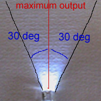
The 'beam pattern' such as 15 or 50 degrees refers to the total angle in which the light output has dropped to about half of that measured in-line with the axis of the LED so, for the Nichia it would be roughly plus and minus 25 degrees about the axis of maximum output [see diagram below].... and the term candela is the modern SI unit of luminous intensity: 1000 milicandelas [mcd] = 1 candela [cd].
For the technical minded: "The candela is the luminous intensity, in a given direction, of a source that emits monochromatic radiation of frequency 540 x 1012 hertz and has a radiant intensity in that direction of 1/683 watt per steradian." This was introduced in 1979. ( SI unit definition.)
|
|
The above diagram illustrates beam pattern, the red line showing maximum light output and the two black lines were the light has fallen to about 50% of the maximum.
Precautions on using LEDs.
Light emitting diodes like to be wired up in one direction only across the supply and will only light up if this is correct. Reversing the supply the LED will not light and you can destroy it. Typical maximum reverse voltage for a high luminosity LED like the Nichia discussed here is 5 volts - ie: not much more than typical battery volts. I have reversed mine many times during my experiments because I have no colour coding on my LED supply wires but the reason I get away with it is because I set the light level control to minimum before I connect up - enough to see if the LED just lights or not - I always do this. LEDs like to have a resistor in series with one of the leads, this limits the maximum current and sets a safe working voltage so you should not connect them directly across a battery. When soldering the LEDs you should use a low wattage soldering iron and hold a pair of pliers between the iron and the LED and finally try to avoid acute bending of the wires very close to the body.
Light characteristics from three selected 'white' LEDs.
|
|
|
|
|
|
|
|
|
|
|
|
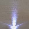
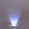
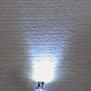
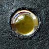
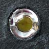
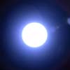
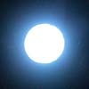
The top row shows beam patterns of 3 different 'white' 5mm LEDs projected on card, the left and middle are of unknown manufacturer but on the right is the Nichia that I bought specifically for experimenting with microscope illumination. The camera was held at the same distance throughout and shows that the lefthand LED has a narrow beam width with side lobes, not ideal for microscopy. The centre LED was borrowed from a piece of portable radio equipment specifically designed for lighting up a small area for reading notes in the field, it is extremely bright at its maximum setting but a blue cast especially at lower voltages spoilt some of the bright field images. The righthand Nichia has the best overall characteristics, under normal brightfield work the background is excellent and uniform and as with most of these LED's the colour balance remains roughly the same throughout its working voltage - a distinct advantage over filament bulbs. A small battery supply and variable lighting control is all that is needed for a self contained lighting system. The settings of the Nikon 4500 were kept the same throughout all the tests.
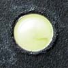
The middle row shows the LEDs with no voltage applied as they would appear in situ in the mount of the Periplan eyepiece [see below], the lefthand LED although appearing to have a uniform illuminating area has the poorest beam pattern for microscopy. The centre LED which has a construction similar to the Nichia has a better beam pattern but a light blue cast when powered, on the right the Nichia which appearing to have the smallest illuminating area has the best beam characteristics and white balance.
The bottom row shows the LEDs powered for roughly the same luminosity [which requires different settings on my variable voltage battery supply] to show the significant differences in colour cast.
A word of caution: There may be a tendency to go for the brightest LEDs you can find, this could be a risk to your eyesight since the most powerful 5mm LEDs of today are so bright that looking at them at their maximum brightness at close range or especially under the microscope could be damaging to your eyes. The Nichia that I purchased has moderate maximum brightness by today's standards [around 2000 mcd at 4.0 volts] and Nichia supply a full set of data so you can judge your own requirements but compare this to some of the brightest LEDs of similar size - they can exceed 12000 mcd!. Another area of LEDs which you should be aware of are the ones capable of generating ultra-violet [UV], the Nichia range I selected mine from have graphs which show a sharp cut-off in light output before the UV end of the spectrum but there is no guarantee of this if you buy from unknown sources. In theory LEDs capable of UV output should come with warning labels on the bags similar in design to those that you may see on the lasers of portable CD players, you should get this by default from a reputable components supplier but from some suppliers on the Internet this may not be the case - a very good reason to obtain them from a company and supplier where you can check all the details beforehand.
Summary of the typical working conditions for the 5mm Nichia NSPW510BS 5mm 'white' LED I used:
|
working voltage [volts] |
typical current [mA] |
direction characteristics [degrees] |
typical brightness at 3.6 volts [mcd] |
|
3.6 |
20 |
50 |
1800 |
[Note that Nichia now supply a 'warm white' LED under the code NSPL510S which may be well worth considering for microscope use, it has working conditions very similar to the standard 5mm white series and could be directly substituted for the one I used].
LED illuminator using a Leitz Periplan eyepiece.
|
|
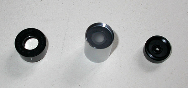
Above left: Periplan top lens, middle: showing the diffuser sitting on the baffle and right: the LED holder which takes 5mm LED's, all using the original Periplan assembly.
The LED housing for the Swift 'Model P' microscope consisted of a 10x Leitz Periplan eyepiece with the bottom lens element removed [put it in a safe place, you might need it again and remember which way round the lens was mounted] and a round metal disc substituted where the lens would be held by the original screw ring. The disc was covered with black card and both drilled to accept a 5mm plastic holder for the LED, these are available from electronic component suppliers when you order the LEDs. After testing several different diffusing materials the best compromise between light loss and good background uniformity was the plastic sheet that covers film negatives received from the developers. This material is almost transparent and found to be better than tracing paper. The diffuser was cut using a sharp knife around a 1 pence piece [if you are in the UK] - a perfect fit in my Periplan eyepiece and held in place because of its very fragile nature by a cardboard ring as shown above centre. After a lot of experiments I have found the best place for this is almost touching the LED which conveniently happens to be where a small baffle is located in the Periplan. If you managed a good fit a couple of small pieces of Blu-Tak should hold it in place but I have a large assortment of rubber O-rings and one of these fitted perfectly. Note that the use of ground glass elements directly in front of the filament lamp were used in designs like the Zeiss standard of the 1960's and Wild M20 lamp assemblies to remove some of the problems associated with more compact filaments so this technique is by no means new.
One important thing to remember when using LEDs as a light source in micoscopes is accurate centring in your light assembly, because of the small illuminating area of LEDs compared to filament bulbs it is very important not only to get the centring correct but also even more important is to make sure the LED is not sitting at an angle in its mounting hole, even small errors here may mean the efficiency is reduced and you make get dark areas looking down the microscope. If you use a proper LED holder like I have used you should not have any problems because they 'click' into place.
Performance : I found that the above illuminator together with the Nichia LED gave good even lighting even with lower magnifications such as 5x and 10x Swift objectives and the best performance for 40x and above objectives occurs when you unscrew the Periplan top lens and just use the LED and diffuser together with re-adjusting the condenser for optimum lighting looking down the eyepiece tube with the eyepiece removed. Placement of the illuminator I have found to be optimum when the diffuser roughly lines up where the original mirror would be in older microscopes, if you raise the assembly to just below the condenser you do not see a sharp outline of the condenser diaphragm when stopping down for best contrast in brightfield illumination with the condenser in its correct location. I used this set-up for crossed-polar work and found there is plenty of light both visually and for digicams like my Canon Ixus 400.
|
|
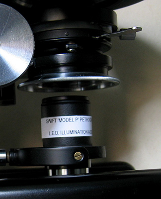
Swift 'Model P' LED illuminator using the Periplan eyepiece which sits in the original mirror mount via a home made carrier made from a fibre glass base plate drilled to accept the two brass mounting screws and cardboard tube to hold the eyepiece. Although the top of the Periplan is near to the condenser the actual diffuser in front of the LED is close to the original point where the mirror would have been. This unit worked well and was used as a pre-cursor to a more sophisticated assembly for my LOMO student stand. Using the original mirror mount allows accurate centring of the light and provides excellent variable oblique illumination by moving the light off axis, this method of mounting could be used with a number of older microscopes that use mirrors. The light from LEDs tends to be very well controlled preventing problems with glare particularly in high power objectives but I did experiment with a cardboard field stop with the Periplan illuminator [sat on the top lens] for the 10x Nikon objective which did enhance the contrast.
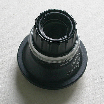
LED illuminator using an old darkroom photo developing lens assembly.
|
|
|
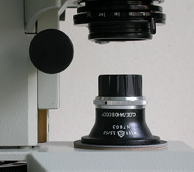
Part of the LOMO student stand showing the illuminator, this time I used a Russian lens assembly from a redundant darkroom photoenlarger which also blends very well aesthetically with the stand! The assembly consisted of 3 lenses, after some experimentation I removed one of them and repositioned the other two in their mounts to provide an excellent illuminator. The advantage of this unit is that it has a variable diaphragm so I now effectively have a field diaphragm for the LOMO providing a little better contrast especially with the LOMO 40x water immersion objective. The cardboard disk seen below the assembly allows free movement of the light beneath the condenser for accurate centring which is easily achievable by closing down the diaphragm. Again, I can get various degrees of oblique illumination without the need of a special condenser, the right picture shows a close-up of the top of the light, beneath the screw down ring I fitted a glass cover slip in a card mount to keep dust from settling on the lens and diaphragm. The aluminium ring adjusts the aperture of the diaphragm. Humbrol black enamel paint was used to improve the finish of the top section.
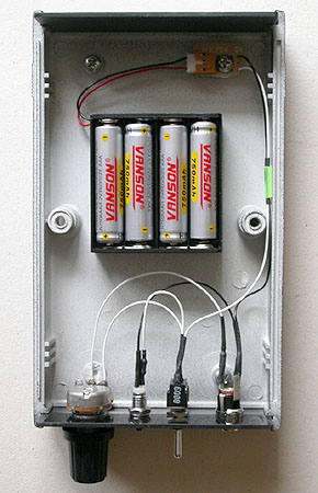
The battery supply unit.
|
|
This very simple battery supply consists of 4x 750mAh AAA rechargeable NiMh batteries in series which are easily removed from the case for recharging, an on-off switch, a 10k ohm variable resistor and a fixed 68 ohm resistor both in series with the LED. The variable resistor changes the brightness of the LED and the fixed resistor limits the current and sets the maximum brightness governed by the safe maximum working voltage which I chose as about 3.6 volts, although the Nichia can be used up to 4.0 volts. Typical fully charged batteries supply about 5.0 volts, a low current front panel LED completes the unit. The lighting is so efficient at the brightness levels I have been using I have only recharged the batteries once since building it although theoretically the batteries should supply the LED at maximum brightness for about 37 hours.
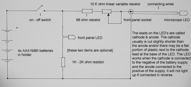
Circuit diagram for the battery unit.
|
|
The component values are nominal, for instance I like the microscope LED to go right down in level with my light control set fully anti-clockwise but you may wish to have better control at the higher brightness levels which suggests a variable resistor of say 1K ohm [1000 ohms], also the series resistor for the front panel LED can be changed quite dramatically depending on how bright you like your on-off indicator from say 1K ohm to 3.3K ohm [standard values].
Battery unit assembled.
|
|
The battery supply is very small and portable so I can easily move the microscope and light to different parts of the house if necessary and, unlike external Köhler lamps it only takes a few seconds to re-align the lamp.
Full details of Nichia lamp LEDs can be found on their website: www.nichia.com you may have to enter a few personal details on their website to obtain in depth information.
Final comment: Although I have used a Leitz Periplan eyepiece and a 30 year old enlarger lens assembly for my illuminators, the small nature of LEDs make it possible to try all sorts of combinations from whatever eyepiece tubes, diffusing material and lenses you may have. With regards to the battery supply you can easily get away with a flat alkaline 4.5v torch battery and a couple of wires and paper clips for connectors as I did for all my preliminary tests but it is not a good idea to connect the LED directly across the battery there will be excessive current flow. Don't follow my ideas rigidly.... experiment and you may find much better combinations. If you live in the UK Maplin Electronics on-line store can supply the LED I used under the **code NR73Q and can also provide a suitable plastic case, control knob, rechargeable batteries, variable resistor, fixed resistors and hook up wire etc.... have fun!
** If you type in NR73Q into the product search box you will get short details of the LED and Maplin have kindly provided the 15 page Nichia pdf file giving full details and safety precautions, as always companies like Nichia and suppliers like Maplin can withdraw particular LEDs at short notice and bring out new ones with different codes so you may have to substitute replacement types in the coming months.
The end.
Comments to the author, Ian Walker, are welcomed.
Published in the May 2004 edition of Micscape.
Please report any Web problems or offer general comments to the Micscape Editor.
Micscape is the on-line
monthly magazine of the Microscopy UK web
site at
Microscopy-UK
© Onview.net Ltd, Microscopy-UK, and all contributors 1995 onwards. All rights reserved. Main site is at www.microscopy-uk.org.uk with full mirror at www.microscopy-uk.net .