Resolving Low Contrast Microstructure Using Transmitted and Reflected Circular Oblique Illumination (COL)
Ted Clarke
Retired Materials Engineer
The term circular oblique illumination (COL) was coined by Paul James in his numerous articles in Micscape. An earlier publication by Willis Matthews called this “hollow-cone illumination.”1 Matthews notes that “hollow-cone or annular brightfield illumination can give contrast and resolution superior to that obtainable with narrow-pencil illumination and under favorable conditions comparable to that obtained with phase optics.” Matthews also notes that the dot pattern of Pleurosigma angulatum can be resolved with a 0.50 N.A. objective using COL. Kodak, in the 1935 edition "Photomicrography, An Introduction to Photography with the Microscope", calls this illumination in the reflected light microscope “conical illumination.”2 Leitz previously marketed the Heine illuminator for transmitted annular (hollow cone) illumination. The numerical aperture (N.A.) of the Heine condenser’s annular illumination can be adjusted to match the phase annuli in phase contrast objectives. The N.A. can be increased to provide darkfield illumination or COL. The instructions for the Heine condenser call the annular illumination just falling within the N.A. of the objective, what Paul James calls COL and Frithjof A. S. Sterrenburg calls extreme annular illumination, “brightfield with very rich contrast.” Osamu OKU has proven that the great contrast effect of COL can be obtained with fully corrected, modern Nikon objectives of high N.A. His image of Amphipleura pellucida recorded with COL and a 1.40 N.A. objective is superb. Willis Matthews and Frithjof A. S. Sterrenburg offer hypotheses for the improved contrast with COL. The remainder of this article will deal with my own experiments with COL, especially resolving diatom striae near the theoretical resolution limits of the microscope objectives. The diatom test slide is considered a low contrast subject because the visibility of the striae of pores in the transparent amorphous silica frustules is determined by the refractive index difference between the mountant and the frustules. Resolution tests of modern objectives are done with high contrast but very costly patterns of chrome on glass obtained by electron lithography.3
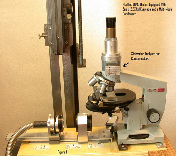
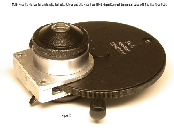
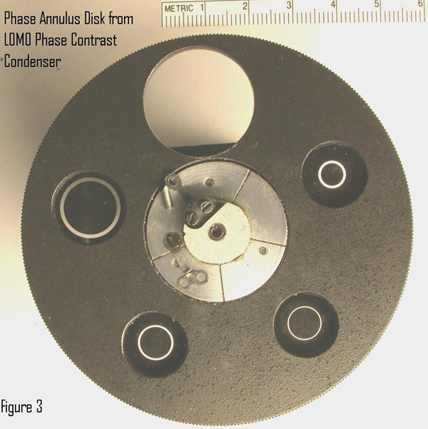
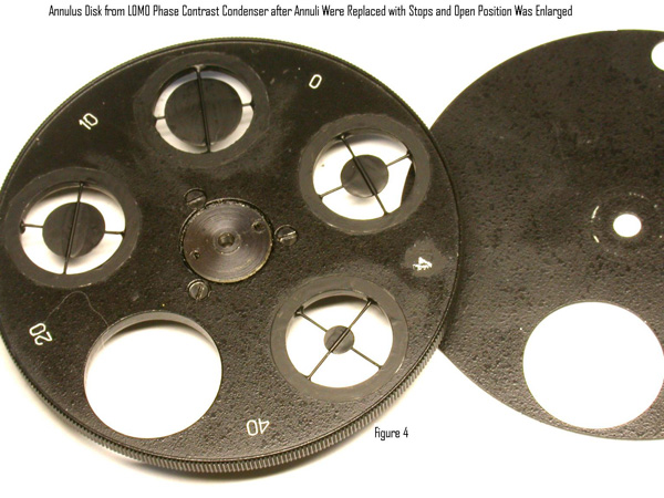
My first awareness of COL resulted from an e-mail interchange with a physiologist in the mid-nineties from whom I learned about reflection contrast to reveal details in live tissue with the reflected light illuminator for the Leitz Orthoplan as described by Ploem.4 He encouraged me to try what I now call COL in transmitted mode with my upgraded student microscope. I had already been experimenting with darkfield to reveal detail in live organisms in lake water samples. I was pleasantly surprised at the great increase of contrast over solid cone brightfield, even with the illumination N.A. reduced to less than half that of the objective. This experiment was done with my modified Monolux student microscope with a fiber-optic light illumination system and home-built condenser. My second student microscope is a LOMO Biolam, also equipped with a fiber-optic source illumination system. The Biolam came equipped with an Abbe condenser. I soon purchased the aplanatic condenser and phase contrast optics for the Biolam. In order to rapidly switch between different illumination modes, I designed and built a multi-mode illuminator for the Biolam using the 1.25 N.A. Abbe condenser with the base from a Lomo phase contrast condenser. The annuli in the wheel were replaced with darkfield stops for the 4X through 40X objectives, with the same stop for darkfield with the 4X objective used for COL with the 40X 0.65 N.A. objective. This condenser is shown in Figures 1-4. The testing of this condenser was done with the Klaus Kemp 8 Form diatom test slide. The main emphasis was imaging Pleurosigma angulatum with the 40X 0.65 N.A. LOMO achromat objective with brightfield, darkfield, oblique, and COL illumination. Resolving this diatom is a common test for a 40X 0.65 N.A. objective. The study included comparisons with brightfield and COL illumination using the LOMO aplanatic condenser. White light was used for the experiments and the digital images were not contrast adjusted with PhotoShop. The photomicrographs were recorded with a Nikon Coolpix 995 camera. This study is described in my Modern Microscopy web article.
A key finding of this study is that the correction for spherical aberration obtained with an aplanatic condenser is quite important for brightfield contrast and much less so for COL with the 40X objective.
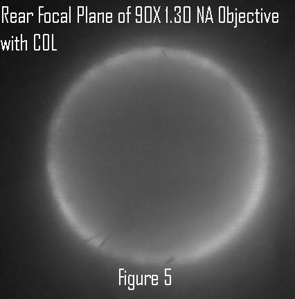
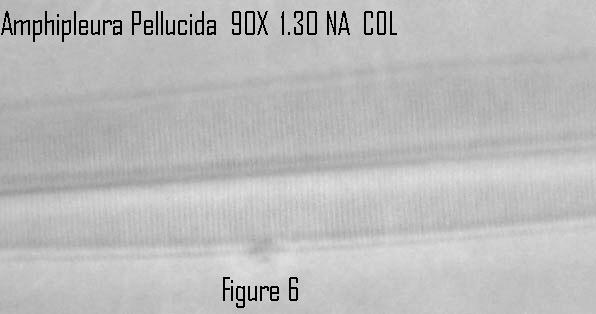
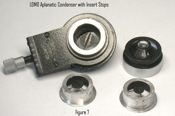
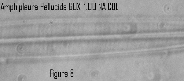
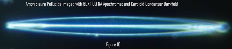
My next use of the diatom test slide was with the LOMO cardioid darkfield condenser and 1.0 N.A. 60X and 1.30 N.A. 90X apochromat objectives formerly available for the Biolam. This time I had the new Olympus E-330 DSLR camera, which I bought for photomicrography because of its 10X live view feature for critical focusing.5 The N.A. claimed by LOMO for their cardioid condenser is 1.2. Since the Biolam and its optics are based upon earlier Zeiss designs, I assumed the condenser N.A. was 1.2-1.3 before I purchased it. This assumption proved to be correct when I saw the annular ring of COL at the rear of the 1.30 N.A. objective, see Figure 5. The striae of the diatom Amphipleura pellucida were well resolved using white light and the cardioid condenser COL, as shown in the grayscale image of Figure 6. As expected, the cardioid illuminator gave excellent darkfield illumination with the diatom test slide, with the diatom Frustulia rhomboides resolved in darkfield but Amphipleura pellucida. I made stop inserts for the LOMO aplanatic condenser for experiments with high N.A. darkfield and COL, see Figure 7. I was surprised to find that I could resolve the striae of Amphipleura pellucida with the 1.0 N.A. 60X objective using COL, but only slight indications of striae with darkfield from the cardioid condenser. The aplanatic condenser was immersed with glycerin held in an immersion fluid retention ring over the front element of the condenser. The evidence of resolving Amphipleura pellucida with the 1.0 N.A. objective and COL is shown in Figure 8 for comparison with the darkfield image in Figure 9. The annular COL at the rear of the objective is shown in Figure 10.
Click image to view master.
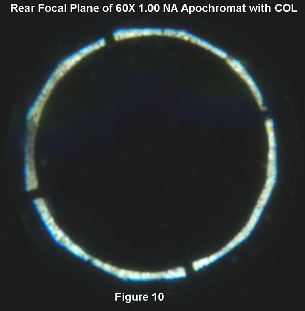
This was the first time I realized that resolution in darkfield could be lower than in brightfield. This has been known for a long time. The COL brightfield, with an outer N.A matching that of the objective follows Abbe’s theory, with the zero and first order diffracted beams within opposite edges of the exit pupil of the objective. Minimum spacing resolved = 0.50 x wavelength/N.A. Abbe’s theory requires at least two diffraction orders to pass through the objective. Martin noted that the N.A. of the darkfield illumination would have to be three times that of the objective for first and second diffracted diffracted orders to enter the objective in order to match the brightfield resolution.6 Martin notes that the resolution with darkfield illumination just exceeding the N.A. of the objective should be “that characteristic of a central beam of very small aperture, so that the performance in resolution will be expected to be much inferior to that obtainable with a full cone of direct illumination.” I believe that the loss in resolution is far less than anticipated by the Abbe theory. The resolution for a 1.00 N.A. objective is 0.27 micrometers with COL according to the Abbe theory and 0.33 micrometers according to the Rayleigh theory for self luminous objects using .550 micrometers wavelength. Thus it is not surprising that this diatom was resolved with COL but not clearly with darkfield illumination. Since this diatom strongly scatters the blue part of the white light illumination in darkfield, the resolution may be about 0.27 micrometers using .450 micrometers for the wave length in the Rayleigh equation. Although I was unable to resolve Amphipleura pellucida with the 1.0 N.A. objective with darkfield, I was able to resolve Frustulia rhomboides with the 1.0 N.A. objective and darkfield from the cardioid condenser. The listed spacing for the striae of Frustulia rhomboides is 0.30 micrometers versus 0.27 micrometers for Amphipleura pellucida. Thus I believe the Rayleigh equation for self luminous objects applies to darkfield illumination
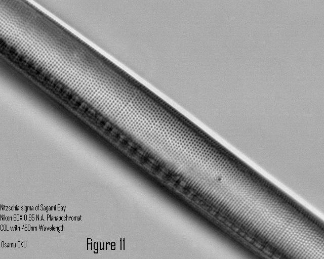
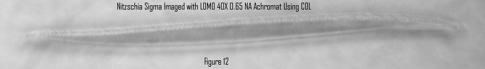
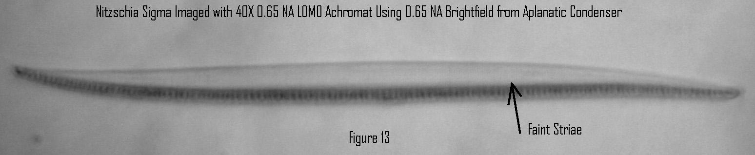
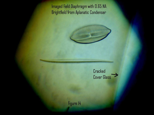
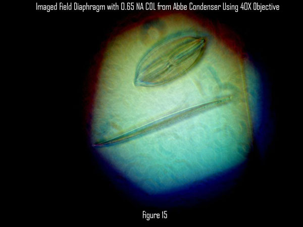
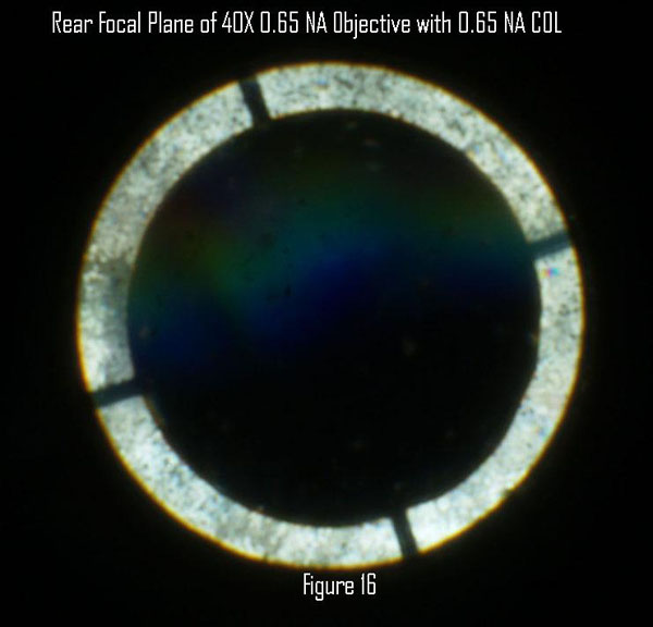
The calculated resolution for a 0.65 N.A. objective using COL is 0.42 micrometers, significantly smaller than the 0.53 micrometer striae spacing listed for Pleurosigma angulatum and consistent with Matthews claim of resolving this diatom with a 0.50 N.A. objective with COL. The listed striae spacing for Nitzschia sigma in the Kemp test slide is 0.44 micrometers. I decided to see if this diatom could be resolved with COL from my multimode condenser and with solid cone brightfield from my aplanatic condenser using white light. I informed Osamu OKU of my attempts to resolve Nitzschia sigma with a 0.65 N.A. achromatic objective. He sent me a superb grayscale image of this diatom recorded with COL using a 60X 0.95 N.A. Nikon planapochromat with 450 nanometer blue light, see Figure 11. I was able to easily resolve striae in Nitzschia sigma with the LOMO 40X 0.65 N.A. objective with COL from my multi-mode condenser as shown in the grayscale image of Figure 12. I was not able to see the striae with the 10X live view of the E-330 camera until after I temporarily inserted a green filter into the illumination beam for critical focusing. Evidently the live view is of lower contrast than the recorded image. The striae were very difficult to observe with full N.A. brightfield illumination. Temporarily inserting a green filter into the illumination beam improved the visual contrast, but the contrast was still too low to focus on the striae with the 10X live viewing. This was another learning opportunity for me. I thought I could focus the microscope viewing through the eyepiece and then slide the monocular microscope under the separately mounted E-330 camera for recording the image. As noted in my previous Micscape article on the E-330, I use an Olympus 28 mm f/2.8 film camera lens in the Olympus MF-1 adapter to record the aerial image viewed at infinity through the eyepiece. The 28 mm wide angle lens is focused at infinity to form a real image on the camera sensor. I learned that the infinity setting for the 28 mm lens had to be preset with the camera mounted on a tripod viewing a far distant object. Once I had learned this, I was able to document with the grayscale image of Figure 13 showing evidence of resolved striae in brightfield. The original color images for Figures 12&13 were moderately contrast enhanced with PhotoShop prior to conversion to grayscale. Downsized color images in Figures 14&15 show the images of the field diaphragms and color effects from the lack of chromatic aberration correction in the condensers. The narrow N.A. range of the COL with the Abbe condenser allows the field diaphragm to be resolved about as well as with the aplanatic condenser with conventional brighfield. The rear of the 40X objective with COL is shown in Figure 16.
Click image to view master.
Click image to view master.
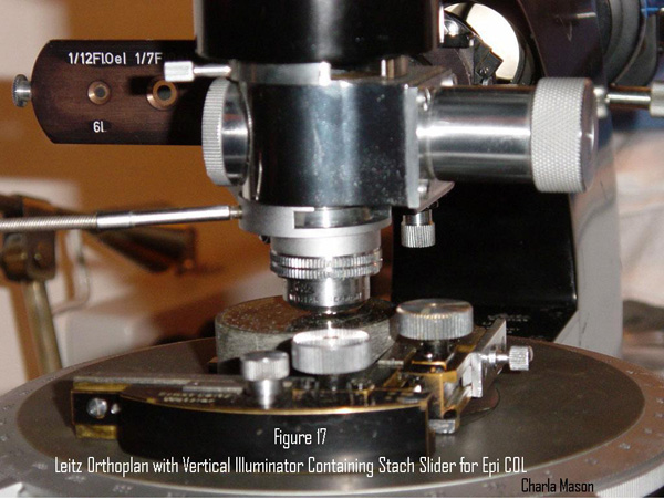
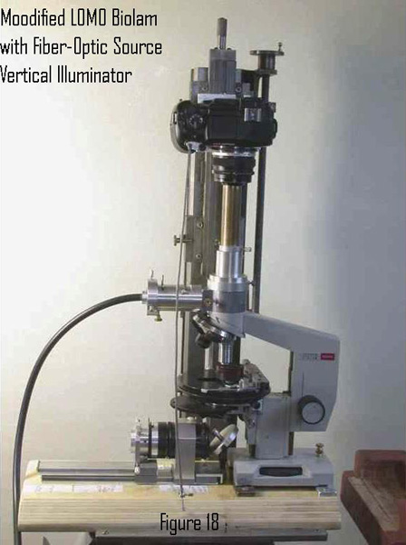
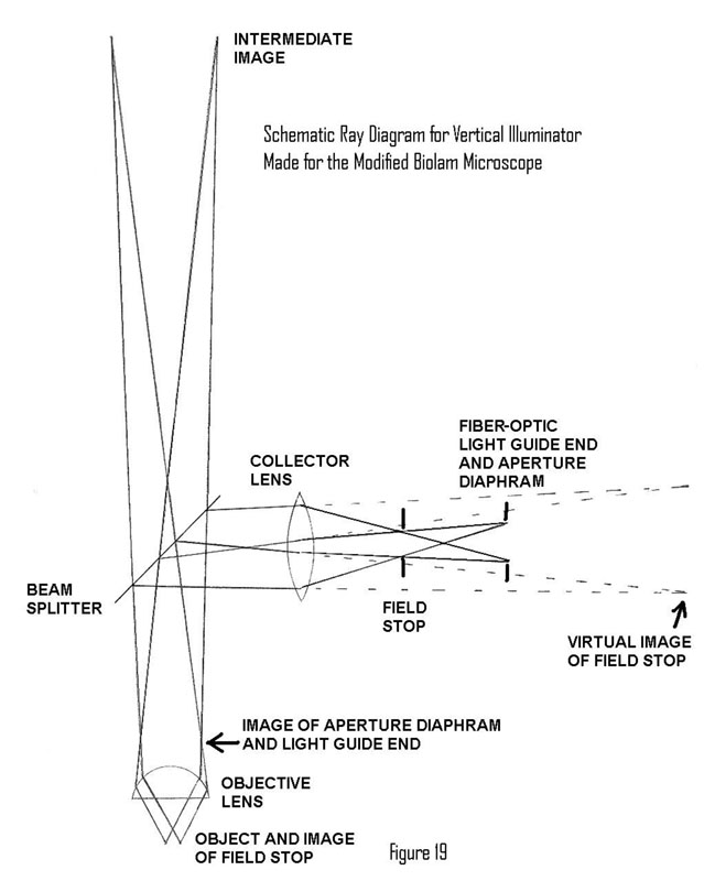
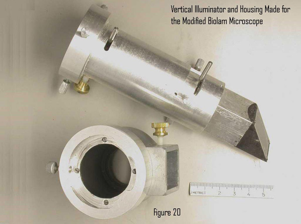
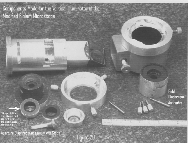
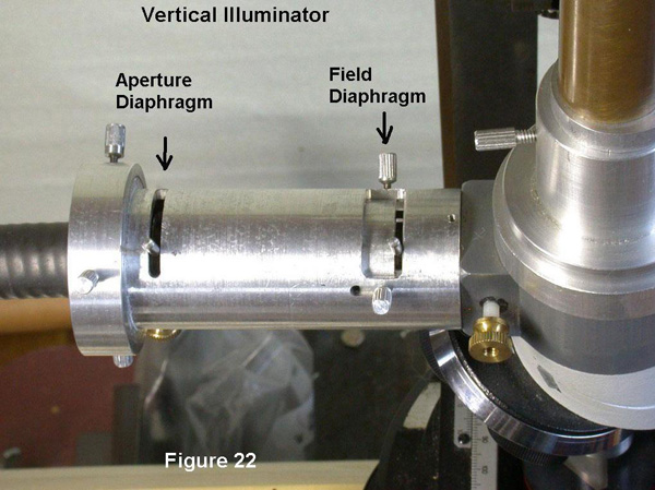
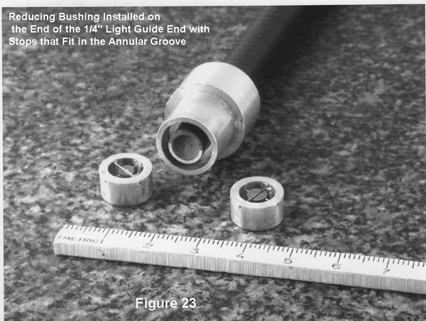
My career as a metallurgist was spent using the reflected light microscope. I learned about improving contrast in reflected light from with COL (annular brightfield) from the old books in the metallography laboratory. These included the previously mentioned Kodak book on photomicrography and a book on metallographic practice by George L. Kehl.7 This technique was no longer used by metallurgists at the time I started my career. The vertical illuminator for the Leitz Orthoplan was available with a Stach slider of stops to improve brightfield contrast of low reflectivity sections of coal. Charla Mason sent me the photograph for Figure 17 showing the Stach slider installed in her Orthoplan. The invention of antireflection coatings for the microscope lenses provided enough contrast improvement to make the method obsolete for most applications. Costly DIC now handles the low contrast opaque specimens. I designed the reflected light illuminator for my Biolam so it included COL capability to satisfy my curiosity about its usefulness with antireflection coated optics.8 My modified Biolam with the reflected light (epi) illuminator is shown in Figure 18. An operating ray diagram for the illuminator is shown in Figure 19. The illuminator and mating housing made for the Biolam are shown in Figure 20. The internal components of the illuminator are shown in Figure 21. Figure 22 is a close-up view of the illuminator after installation on the Biolam. The illuminator can be used with either ½ “or ¼” fiber-optic light- guides. The larger size is intended for darkfield with metallurgical objectives having both capabilities. The ¼” light-guide is more convenient to use because the COL stops can be quickly installed inside the adapter bushing over the end of the smaller light-guide end shown in Figure 23 without removing the aperture diaphragm assembly to install a stop on the other side of the diaphragm.
Click image to view master.
Click image to view master.
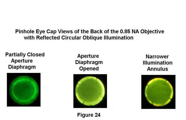
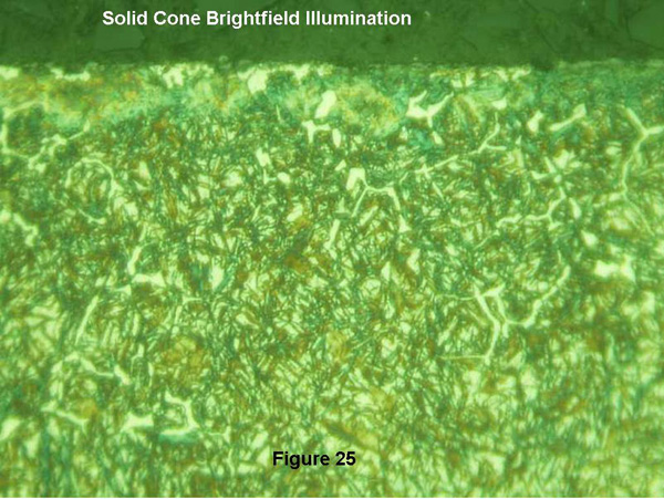
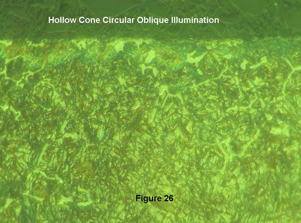
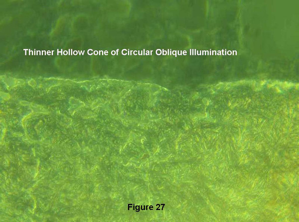
I obtained a nital etched metallographic section of a case hardened gear tooth with a carbide network at the tooth surface to test the new illuminator. I expected the harder carbide network to show evidence of relief polishing with COL. An antireflection coated 50X 0.85 N.A. 215mm tube length Bausch and Lomb metallurgical objective was used to examine this specimen. The position of the field diaphragm in the illuminator can be adjusted to cover a tube length range of 160-215 mm. A longer drawtube was used with this objective as shown in Figure 18. The effect of two stop sizes to vary the effect of COL on the image contrast was studied. Figure 24, recorded using a pinhole cap in place of an eyepiece to view the rear the objective, shows the two annuli widths used. The aperture diaphragm was set to match the 0.85 N.A. of the objective for the comparisons of COL with the brightfield image of Figure 25. Figures 26&27 demonstrate the increased contrast with COL, with a thinner hollow cone of COL giving significantly more contrast. It is unfortunate that reflected light COL (extreme annular brightfield) is unknown to the current materials science and engineering community. It would be very inexpensive to add this capability to modern reflected light microscopes.
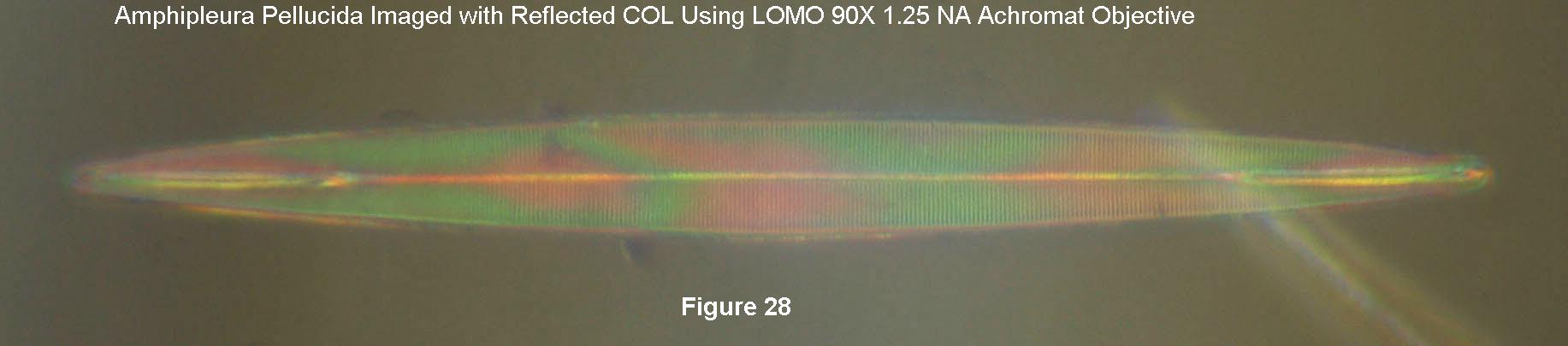
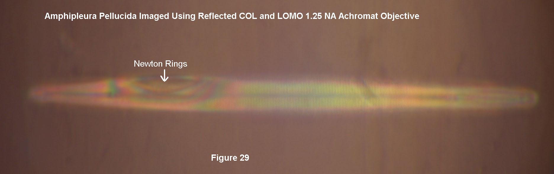
Since I was aware of use of polarized COL for the reflected light contrast mechanism of Ploem, I decided to determine whether I could resolve Amphipleura pellucida diatoms in a strew slide obtained from Klaus Kemp. I used the LOMO 90X 1.25 N.A. biological objective with reflected COL. I was surprised to see that the striae were resolved with higher contrast than with transmitted COL and the more highly corrected 1.30 N.A. apochromat, compare Figure 28 with Figure 6. The darkened background was expected based on the Ploem article. What I did not anticipate was the interference microscope effect evidenced by the color bands in Figure 28. There is a reflection of the illumination from the interface between the underside of the cover glass and the mountant which can interfere with the light diffracted from the diatom surfaces in contact with the cover glass. The diatom is nearly parallel to the cover glass interface in Figure 28, giving rise to the interference color bands. The diatom in Figure 29 is less well aligned, giving rise to the colored Newton rings.
Hopefully this article will encourage further use of COL by devoted amateurs and even some professional microscopists. Transmitted COL can be obtained with stops not quite large enough to give darkfield. My nature center article shows simple methods for obtaining darkfield capability with an Abbe condenser.
All comments to the author Ted Clarke are welcomed.
References
1 Matthews, W. W. “The Use of Hollow Cone Illumination for Increasing Image Contrast in Microscopy”; Transactions of the American Microscopical Society, Vol 72, No. 2 (Apr, 1953), pp. 190-195.
2 Photomicrography, An Introduction to Photography with the Microscope; Eastman Kodak Company: Rochester, N. Y.,1935.
3 Brenner, M. “Imaging dynamic events in living tissue using water immersion objectives “;
American Laboratory, April 1994.
4 Cornelese-Ten Velde, I,Bonnet, J.,Tanke, H. J., Ploem, J. S. “Reflection Contrast Performed on Epi-Illumination Microscope stands: Comparison of Reflection Contrast and Epi-Polarization Microscopy”; Journal of Microscopy 1990,159,1-14.
5 Clarke, T. M.”Using the Olympus E-330 DSLR Camera for Photomicrography”: The Microscope 2007,55.4,163-172. Download a copy of ref. 5 courtesy of Ted Clarke.
6 Martin, L. C. The Theory of the Microscope; Blsckie,1966, 297-300.
7 Kehl, G. L. The Principles of Metallographic Practice; McGraw-Hill Book Company, 1949.
8 Clarke, T. M. “Reflected Light COL (Circular Oblique Illumination), an Almost Forgotten Technique”; The Microscope 2008, 56.2, 53-60. Download a copy of ref. 8 courtesy of Ted Clarke.
Published in the November 2010 edition of Micscape.
Please report any Web problems or offer general comments to the Micscape Editor .
Micscape is the on-line monthly magazine of the Microscopy UK web site at Microscopy-UK
©
Onview.net Ltd, Microscopy-UK, and all contributors 1995
onwards. All rights reserved.
Main site is at
www.microscopy-uk.org.uk
with full mirror
at
www.microscopy-uk.net
.