|
A Restoration Project by Fritz Schulze, Canada |
The sight of a broken instrument, toy or doorlock raises in me the irrepressible urge to fix it. I am an incorrigible tinkerer. No wonder as I hail from Swabia, an area in Southern Germany the inhabitants of which have the reputation of being thriftier than Scots: waste not, want not.
At home I am in constant conflict with “she who must be obeyed”, who considers the slightest deterioration of her kitchen machine reason enough to go out immediately and buy a new one. And SHE is the Scot in our family, go figure!
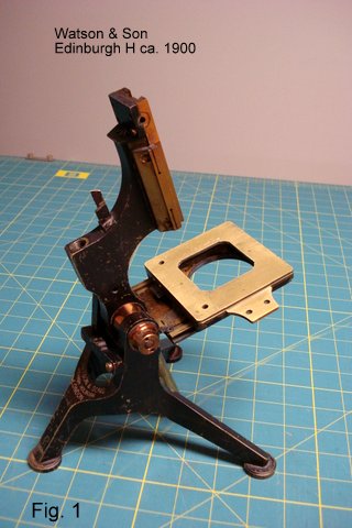
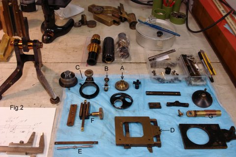
So when I spied on eBay the incomplete skeleton of a Watson microscope “for parts” I couldn't resist the temptation to bid – and I got it for $25! (Fig. 1). This acquisition gave me an excuse to dig into my box of bits and pieces of microscopes to see if it offered enough parts to essay a completion of said skeleton. Indeed, I found an old black Spencer tube with extension, a triple nosepiece, part of a Zeiss stand with a suitable fine focusing mechanism, some racks and dovetails, condenser and mount (Fig.2). The major shortcoming were the gears (pinions) as they are usually the first items cannibalised from an unwanted microscope.
My restoration project could be divided in 5 steps:
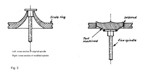
1- The fine adjustment. This was entirely missing from the Watson stand. I decided to try and adapt the corresponding parts from an old incomplete Zeiss stand. It immediately became obvious that I could not use the conical focusing knob as is because the precision spindle was too far recessed (Fig. 2, A+B). My solution was to redesign the knob with the circular mm graduation to a flat configuration with the spindle protruding far underneath which left it also closer in appearance to the original (Fig. 3). I unscrewed the central spindle part, turned the conical part off, inserted a flat centre piece with a space underneath it to insert and solder fast the spindle.
Fortuitously, and I could hardly believe it, the nut of the fine focusing spindle fitted into the thread of the Watson stand. I had only to cut it off at the line indicated in the picture (Fig.2-B) and interpose a short rod to reach the lever of the mechanism.
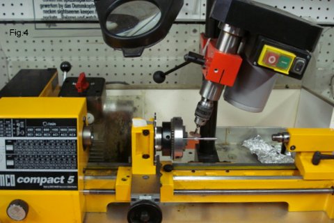
2- The coarse focusing mechanism. I had to replace the guiding rod of the old tube by a dovetail in order to fit it to the Watson stand. I had a suitable rack but no matching pinion. From previous repair jobs I had already experience in manufacturing small pinions. I installed my dividing head on my lathe, set the milling head at the appropriate angle, and using a thin grinding wheel from a Dremel tool set to cut the gear. The diameter could be ascertained from the distance of bearing to rack, the number of teeth was both calculated and experimentally obtained by a plasticine imprint. To be sure that I don't miss the proper position of the dividing head, I stuck small pieces of paper to each position. (Fig. 2-E and Fig. 4). The final fitting was done with a needle file under a stereomicroscope.
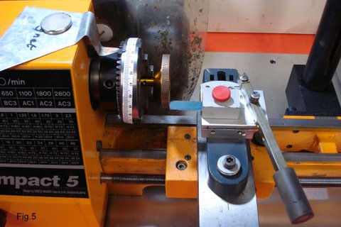
The large focusing knobs I made too large in my enthusiasm (I ought to have checked an original picture of the Watson microscope for the proportions!). They are fixed on the shaft with a grub screw. The knurl proved again a problem as my lathe does not provide for burring, so I use a home-made cutting device (Fig. 5). I wrapped a paper mm-scale over the chuck, set an index (held with a magnet) and cut each groove by pushing a specially ground piece of a hacksaw by means of a lever across the workpiece. Laborious and slow, again with more patience and repeated cutting, the grooves would have been deeper.
The Spencer trademark on the tube I filled with body filler, sanded it smooth and then painted the tube black.
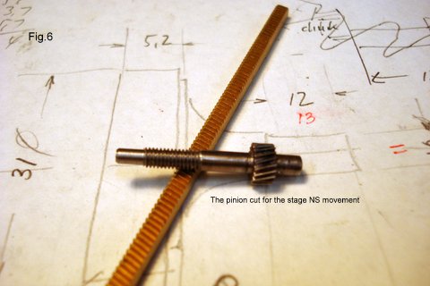
3- The mechanical stage. This again was a major stumbling block as all essential items had been removed. For the N-S movement I could adapt a short rack, but again had to manufacture a shaft with a pinion and the control knob (Fig. 6). The E-W movement posed a particular challenge. The original probably has a multi-start spindle for fairly quick movement. I figured a regular thread would be too slow. Then an idea struck me: the condenser mount has a multi-start spindle for the vertical adjustment. Could this be adapted?
In the end I decided to cut the condenser mount at the line (Fig. 2 – C) and screw it with its spindle and knob to the underside of the stage plate (Fig. 2 – D and Fig. 7). The end of the central stationary shaft I attached to the N-S stage plate. The system works perfectly and allows a range of 12 mm. The N-S graduation with vernier was still there, but for the E-W movement I had to make a plate with graduation for the existing vernier (Fig. 8).
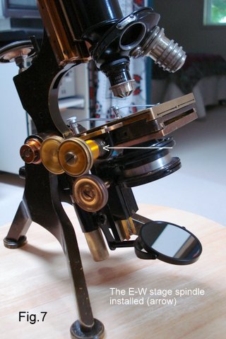
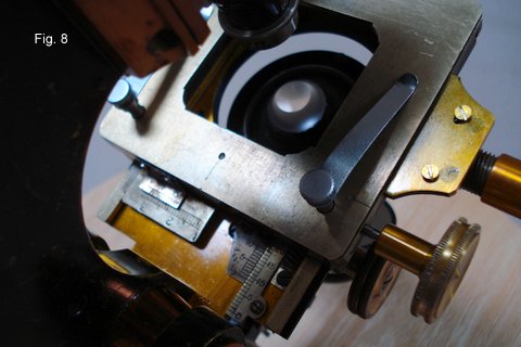
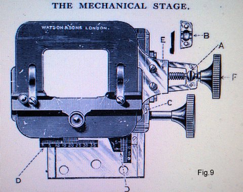
Fig. 9 shows in detail the original Watson mechanical stage, quite a bit different!
4 – The condenser mount. The remainder of the ring-shaped condenser mount I attached to a dovetail block which glides on a counterpiece screwed to the stage carrier. The proper distance had to be ascertained for the condenser to be in the optical axis. For this I peered through the empty tube and used a paper template to mark the centre. I had enough dovetail parts with rack and pinion to finish the vertical condenser movement Fig. 2-F). The condenser itself had to be slightly modified to allow it to reach close under the slide.
5 – The mirror mount. The basic tubular shaft was there. A piece of copper tube (Fig. 2-G), slotted for better friction, came from a standard 5/8” plumbing tube. The rest of the gimbal linkage was no problem, a fine plane-concave mirror from Zeiss (anachronistically surface coated!) completed the arrangement.
After all parts had been cleaned, painted, lubricated and reassembled, completed by the triple revolving nosepiece, an eyepiece, and a pair of stage clips, my revived Watson microscope looked deceptively like the original Watson Edinburgh model H (Fig.11), more or less, almost, not quite, oh well.....
Here in Fig. 10 it is in all its glory. It looks really great on the mantelpiece! As for the image quality, this depends entirely on the old objectives I used, besides, the condenser cannot be centred. After all, you have to make some allowances.
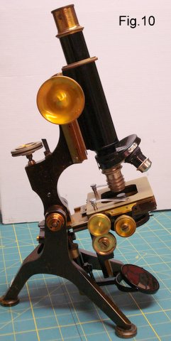
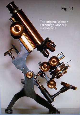
Image right from Ian Walker's article 'Watson Edinburgh Stand 'H'', Micscape July 2006.
Comments to the author Fritz Schulze are welcomed.
Vineland, ON, Canada
Nov. 11, 2015
Published in the November 2015 edition of Micscape.
Please report any Web problems or offer general comments to the Micscape Editor .
Micscape is the on-line monthly magazine of the Microscopy UK web site at Microscopy-UK
© Onview.net
Ltd, Microscopy-UK, and all contributors 1995 onwards. All rights
reserved.
Main site is at www.microscopy-uk.org.uk.