Notes on simple polarisation
experiments with micas using a student microscope.
(with an illustrated footnote on 'mica in the landscape'
around the author's home).
by Dave Walker, UK
If like the author, you're a fellow microscopy enthusiast exploring what 'gentle' optical mineralogy can be accomplished with a student microscope, then micas are very rewarding subjects to study. Micas are well known for their ready ability to cleave into thin sheets, so they offer an opportunity for some simple thin section polarisation studies of this mineral. Neither specialist slide preparation methods nor a dedicated polarising microscope is required for the qualitative studies, in which interference colours and interference (conoscopic) figures can be demonstrated.
Sourcing and preparing the mica: Micas are sheet silicates, two of the more common micas are muscovite, an almost clear form and biotite, which is very dark. These two micas can be readily obtained for a nominal sum from geology suppliers. Muscovite, as my brother remarked in his recent article on polarising microscopes, can also be found in redundant electrical apparatus. The author found muscovite from this latter source easier to handle cf. the rough mineral sheets from a geology supplier.
|
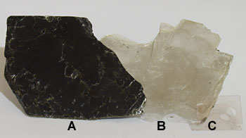
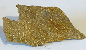
Micas:
A - biotite, B -
muscovite; both from a geology supplier. |
Using a very sharp edge like a razor blade, thin flakes can be cleaved off the mica samples typically obtained from the suppliers. With care, flakes of varying thickness can be obtained. They only need to be a few mm square for the studies. See below for desired thickness. The flakes can be dry mounted under a coverslip. Thin strips of Sellotape along two opposite edges of the coverslip can hold the flakes temporarily secure. Permanent slides with a suitable mountant can be made if desired.
Safety note: The small quantities of mica being handled shouldn't pose a safety hazard if handled carefully by adults, but avoid generating airborne flakes which could be inhaled and minimise skin contact. Tiny flakes can stick to fingers so avoid rubbing the eyes or exposing sensitive skin when handling the material and wash hands thoroughly afterwards. If sourcing mica from redundant electrical kit, it needs technical expertise to know where and what to look for, and there can be hazards associated with dismantling such apparatus.
Note on using a student microscope:
|
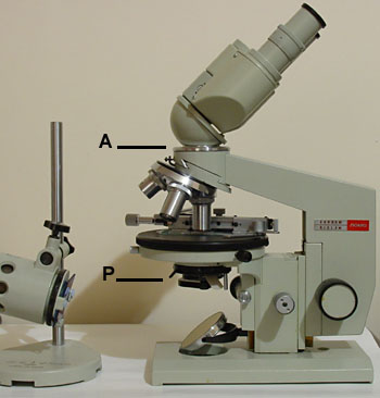
Image right: A typical student microscope, the author's LOMO Biolam. High extinction polarising filters for microscopy are preferable for polarisation studies (a microscope dealer's own brand should be of good quality). The polariser (P) can be placed in the condenser filter tray. For good extinction with 'crossed polars' it's often best to put the analyser (A) below any prisms, here the analyser is on the underside of the binocular head. In the 1970's when purchased, the Biolam was one of the few student microscopes where a centring rotating stage was a standard option at little extra cost, so it's particularly suitable for qualitative polarising studies. Graduated rotating platforms to attach to fixed stages are available quite cheaply from microscope dealers or can be made. For photography the author used a vertical monocular tube i.e. no prisms present. |
|
Studying interference colours and
their variation with mica thickness.
With patience and care, you
may be able to cleave thin flakes off a sample of
muscovite and arrange in order of thickness on a
slide and cover with a cover slip. These will then give a
neat demonstration of how interference colours vary with
thickness when viewed between 'crossed polars'. If like
the author you're not this patient or skilful, an
alternative way is to first cut out a largish 1 cm square
of mica and quite thick, say 0.2 mm or so. Then with a
sharp knife cut smaller squares off with the blade at an
angle. Put these under a coverslip trying not to let
the flakes cleave further, as they may when this
small. Hopefully you should get some flakes with a
'stepped' edge of thinner sheets with a thickness
range that covers to some extent that of a Michel-Lévy
birefringence chart i.e. typically 0-100 µm.
|
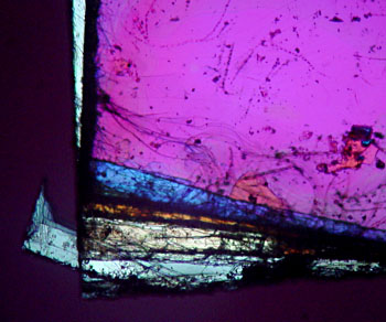
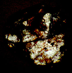
Image right: 'stepped' cut edge of the mica muscovite between crossed polars, 3.5x objective. Five interference colours can be seen with increasing thickness going from image bottom upwards. Whatever colour sequence is obtained from a mica edge can be compared with those on a Michel-Lévy birefringence chart. If the chart shows the lines for values of maximum birefringence (d) of typical minerals, the colour sequence along the line for the figure for muscovite (d = 0.036-0.049, ref. 1) can be followed. In this example shown, the distinctive blue is a 2nd order colour suggesting the mica is ca. 18 µm thick at this point. The brown-orange, grey-white and pale grey below this colour in the image would then correspond to first order colours i.e. of progressively lower wavelength. The predominant purple comprising the full thickness of the flake is a third order colour. |
|
Procedure for using a microscope
for studying interference figures (conoscopic images):
The theory underlying
interference figures and what they can show are well
described in textbooks and online resources (see a selection
at page bottom, the last link gives a clear illustrated overview with practical
examples). The notes
below just cover the barebones practical aspects of
showing the figures with home prepared mica sections and
student compound microscope.
1) Set crossed polars, preferably with
the polariser aligned the conventional east-west in filter
tray. Focus a flake of the mica under a coverslip at low
power. Unlike above, an area of mica of even thickness should
be chosen to fill the field at 40x.
2) Switch to a medium power objective ca. 40x preferably
with a highish NA and refocus. I've found an unbranded
40x/NA0.74 achromatic objective useful as
its undemanding but has a higher than the usual NA0.65 for
an achromatic. (The aim in conoscopic studies is to have a
wide cone of light passing through the sample, and thus a highish
NA objective is needed.)
3) Open the condenser iris fully and ensure back focal
plane of objective is fully illuminated.
4) Take an eyepiece out and inspect the back focal plane
of the objective to view the figure. Rotate the specimen if a rotating
stage (ensure stage is well centred at mag used i.e. mica flake
fills field when stage rotates). For comparison, move the mica out of the field of
view and inspect the back focal plane, to see what false figures
the microscope optics may show (probably due to either objective strain
and/or lower objective element curvature, see ref. 2, page 320). However, muscovite
and biotite demonstrate stronger interference figures and shouldn't unduly
affect the qualitative studies.
(Out of interest, the author had
access to a
dedicated polarising microscope with strain free
objectives, and there was little difference in the nature
of the qualitative interference figures with the same
mica samples used here).
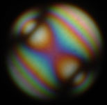
Biaxial figure: Muscovite mica is biaxial (i.e. possesses two crystal optical axes) and can be used to show an interference pattern for a biaxial mineral. Apparently muscovite because of its optical and cleavage properties is particularly suitable for giving a good figure (ref. 1). Cut a square a few mm square from muscovite sheet. It needn't be too thin, ca. 0.1-0.25 mm is fine (ref. 2, experiment 6). Interference figures are worth careful study coupled with a good textbook describing their features (e.g. see ref. 2). How the figures vary with specimen rotation, mica sample thickness and NA of the objective are worth investigating.
For visual qualititative studies the back focal plane of the 40x objective on the Biolam is quite large so the small but crisp image viewed down the eyepiece tube is rewarding. Various ways to magnify and inspect the image can be used depending on kit available i.e. phase telescope, Bertrand lens or Becke lens.
Interference figure photographs below: The figures were projected using a phase telescope. Unaltered images apart from resize (0.7 stop underexposed to retain colour saturation). The black circle is the limit of the objective back focal plane, not vignetting.
|
|
|
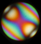
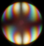
Sequence above:
Typical interference figures seen at the back
focal plane of objective from a cleavage flake
of muscovite mica (dry mount under a
coverslip), as the mica is rotated with respect
to the crossed polars (polariser aligned east-west). The black
bands are called isogyres and the bands of interference colours
are isochromes. |
|
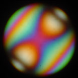
|
|
Images above: Using the same muscovite sample with static interference figure, it's interesting to see how the figure changes with the NA of the objective. Left - 40x/NA0.74 achromat; centre - Zeiss Winkel 42x/NA0.85 apochromat phase (hence black phase ring). right - LOMO 60x/NA1.0 apochromat, oiled (condenser not oiled to slide, so back focal plane not fully illuminated). The higher NA objective gives more detailed figures, although lower NA dry objectives are more practical. |
|
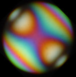
|
|
Image left above: This is the interference figure for a thinner cleavage flake of the same muscovite. Compare this with that for thicker flake with the same orientation (reshown, image right above). (See ref. 2, page 324 for an illustrated discussion of this). |
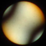
Uniaxial figure: Although the mica biotite is also biaxial, Hartshorne and Stuart in their classic textbook 'Crystals and the polarising microscope' (ref. 2) describe how this mica can be used to demonstrate an interference figure with a 'Pseudo-uniaxial Cross'. Apparently biotite's preferred cleavage is perpendicular to the optical axis and they note that it is 'essentially uniaxial' when a flake from cleavage is inspected under the microscope. As biotite is very dark, a flake of a thickness just sufficient to shine light through is recommended.
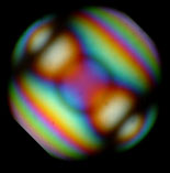
Interference figure photographs below: Because of the strong colour of the biotite and camera insensitivity, these were harder to photograph convincingly. The visual images of the crosses were crisper. (Small 'central hotpsot' is an artefact of lamp at full bore!).
| Images right: Interference figures for biotite sample with 40x/NA0.74 objective. A cross can be seen in the back focal plane. The figure behaves like that of a uniaxial mineral in that the cross is aligned with the vibration axis of the polariser (east-west) and that the cross does not rotate when the section is rotated (contrasting with the complex behaviour of the muscovite biaxial figure above when the specimen is rotated). The cross does separate a little at one position of the mineral, righthand image, (as noted by Hartshorne and Stuart and illustrated in Fig. 323, ref. 1), unlike true uniaxal figures. Concentric rings of interference colours are exhibited for uniaxial minerals, but biotite's strong colour masks any in these figures, so not an ideal example. |
|


Footnote: 'Mica in the landscape' around the author's home.
|
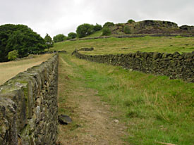
It was only recently that I realised I was encountering mica on my regular local walks in the north of England where I live. The dominant rock in this local areais a type of sandstone. It has been used extensively to make the mortarless, so-called drystone walls, which form field and road boundaries and which typify the landscape in this area. (Image right with walls in foreground and exposed outcrop of the rock upper right). |
|
|
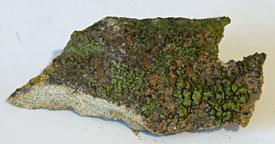
Exposed rock is black with past industrial pollution and/or covered in lichen, algae etc. (Image right, rock fragment 7x3 cm). |
|
|
However, turn the same rock flake over gives the freshly exposed view as seen in newly made walls or broken areas of rock. These fresh faces have areas that glisten in the sun (lighter speckled areas in the image right) and had assumed it was light catching the quartz grains. |
|
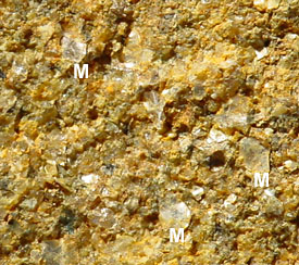
|
Bringing some rock home and studying under the low power microscope it can be seen that the rock contained many areas of mica and it was these tiny flat 'mirrors' that mainly caught the light. (Some mica flakes are labelled 'M', image right, field of view ca. 7 mm.). With a needle it was quite easy to cleave tiny mica flakes from this area of the rock and study under the microscope. |
|
|
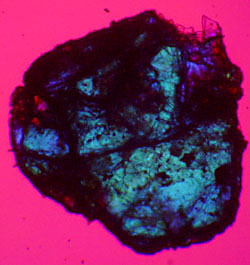
The image above right shows one of these mica flakes under the microscope between crossed polars (3.5x objective, flake ca. 1 mm across). Parts of this flake are so thin they can't be seen as they don't show an interference colour. From the Michel-Lévy birefringence chart, the grey white is a first order colour so the mica is ca. 5 µm thick in this area. The image below it is the same flake with a borrowed l retardation plate placed on top of the slide at 45° to the crossed polars; the flake now shows a second order blue. |
|
Comments to the author Dave Walker are welcomed.
All images by the author, using a Sony S75 digicam. (For photomicroscopy a reversed 50 mm/f1.8 SLR lens was used as a cheap but effective relay lens as described in a recent article).
References
1) 'A practical
introduction to optical mineralogy' by C D Gribble and A J
Hall, (Allen and Unwin, London, 1985). Muscovite entry,
p.94.
2) 'Crystals and the polarising microscope. A handbook for
chemists and others.' by N H Hartshorne and A Stuart.
(London, Edward Arnold, 3rd edition 1960). Experiment 5,
p.472 describes the use of biotite 'To study a uniaxial
interference figure'. Experiment 6, p.474 gives a
description of using muscovite 'To study a biaxial
interference figure'.
Related Micscape articles: It's possible to cleave muscovite sheets to form neat homemade l/4 and l retardation plates, see Ian Walker's article. The use of a prepared rock slide containing biotite to demonstrate pleochroism and to align the polariser east-west is also described.
Selection of polarised light microscopy resources:
'Qualitative
polarised light microscopy' by P C Robinson and S Bradbury, Royal Microscopy
Society Microscopy Handbooks No. 09, (OUP, 1992).
Molecular
Expressions, Optical Microscopy Primer, Specialized techniques, Polarized
light microscopy - an extensive set of illustrated
articles, with interactive tutorials.
The
Michel-Lévy
interference color chart. The microscopist's
magical color key by John G Delly. Illustrated article describing
the chart's uses and history (in the McGrone Group's 'Modern Microscopy'
on-line journal).
Interference
figures - an
illustrated practical introduction by Professor Steven Dutch, University
of Wisconsin-Green Bay, part of Crustal
Materials Class Notes.
Microscopy
UK Front Page
Micscape
Magazine
Article
Library
© Microscopy UK or their contributors.
Published in the September 2003 edition of Micscape.Please report any Web problems or offer general comments to the Micscape Editor.
Micscape is the on-line monthly
magazine of the Microscopy UK web
site at
Microscopy-UK
© Onview.net Ltd, Microscopy-UK, and all contributors 1995 onwards. All rights reserved. Main site is at www.microscopy-uk.org.uk with full mirror at www.microscopy-uk.net .