Fig. 1 (click image for master)
Resolving Amphipleura pellucida Using LED Flashlight Illuminators
Ted Clarke
I am an amateur microscopist who uses low cost, student microscopes at home. These microscopes do not have internal illumination systems. I have designed and built external illumination systems for these microscopes documented in previous Micscape articles. These systems can provide Koehler illumination with an imaged field diaphragm and the end of a fiber-optic light-guide imaged in the rear focal plane of the objective. My most recent article notes that the modified Biolam was using a LED flashlight to illuminate the input end of the fiber-optic light-guide resulting in good darkfield illumination with the 20X objective. Previously I used 150 watt quartz halogen illuminators with an iris to control the illumination brightness. The LED flashlights have become quite common. My curiosity led me to try holding one of these flashlights against the input end of the light-guide and found the microscope illumination to be visually acceptable. I then machined aluminum couplings to attach LED flashlights to the ends on the light-guides. This article describes my use of this illumination with the LOMO 90X 1.25 NA achromat objective to resolve Amphipleura pellucida in a Klaus Kemp 8 Form Diatom Test Slide with both transmitted and reflected COL. My previous article in Micscape (Nov. 2010) on resolving low contrast microstructure and a subsequent version published in Microscopy Today (May 2012, vol. 20, issue 03) demonstrated the resolution of the striae of Amphipleura pellucida with both transmitted and reflected COL with my modified Biolam. In addition to demonstrating use of the LED flashlight illumination, this article explains in more detail how COL and related darkfield illumination were obtained with the LOMO 1.40 aplanatic condenser.
Fig. 1 (click image for master)
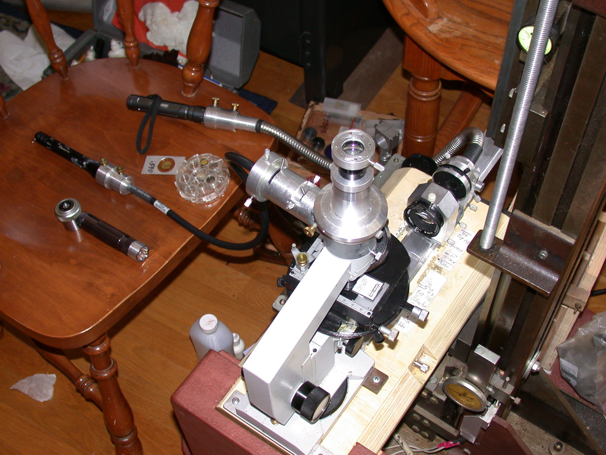
Figure 1 shows the modified Biolam setup with both a vertical illuminator and the LOMO 1.40 NA transmitted light condenser for this study with LED flashlights at the input ends of the light-guides. It is very important to be able to view the rear focal plane of the objective to establish Koehler illumination as well as COL. The simplest way is to remove the eyepiece and view the rear lens element of the objective. I prefer to use a loupe, made from a 25X stereomicroscope eyepiece slipped over the 12.5X Zeiss Kpl eyepiece. The loupe can be seen on the chair in Figure 1. I have astigmatism which cannot be corrected with a microscope focus adjustment. I have an eyepiece cap with a correction lens for my astigmatism seen on top of the eyepiece in Figure 1.The LOMO Multiscope instructions state that the transmitted light condenser should be racked up against the travel stop. The instructions for the 1.40 NA condenser note that a drop of immersion oil can be used on the top lens of the condenser to obtain the “complete aperture of the condenser when operating with immersion objectives.” The rear focal plane of the 1.25 NA 90X objective is shown in Figure 2 with the condenser racked up and oiled. I have previously noted that I had to increase the immersion fluid thickness between the top of the condenser and bottom of the slide to about 1mm in order to obtain the “complete” aperture. Figure 3, 3a is of the rear focal plane of the 1.25 NA objective obtained with a fluid retention cap to maintain a glycerin filled gap of 0.96 mm. A COL stop is imaged along with the end of the fiber-optic bundle with a distinct outer boundary expected for fully filling the aperture of the 90X. Both images were recorded with the loupe over the eyepiece and the 28 mm f/2.8 wide angle lens on the Olympus E330 DSLR focused at infinity. Calculations using the ratio of the illuminated diameters indicate that the illumination NA in Figure 2 is only about 0.8, which does not require immersion fluid on the condenser.
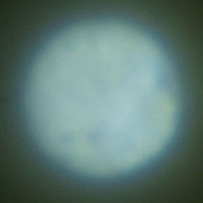
Fig. 2
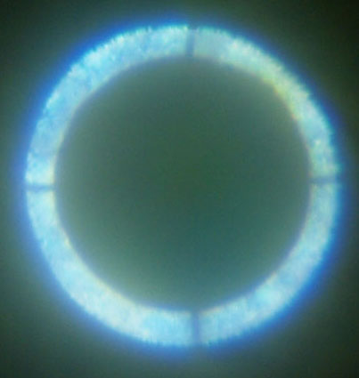
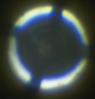
Fig. 3 (transmitted COL) and 3a (epi COL)
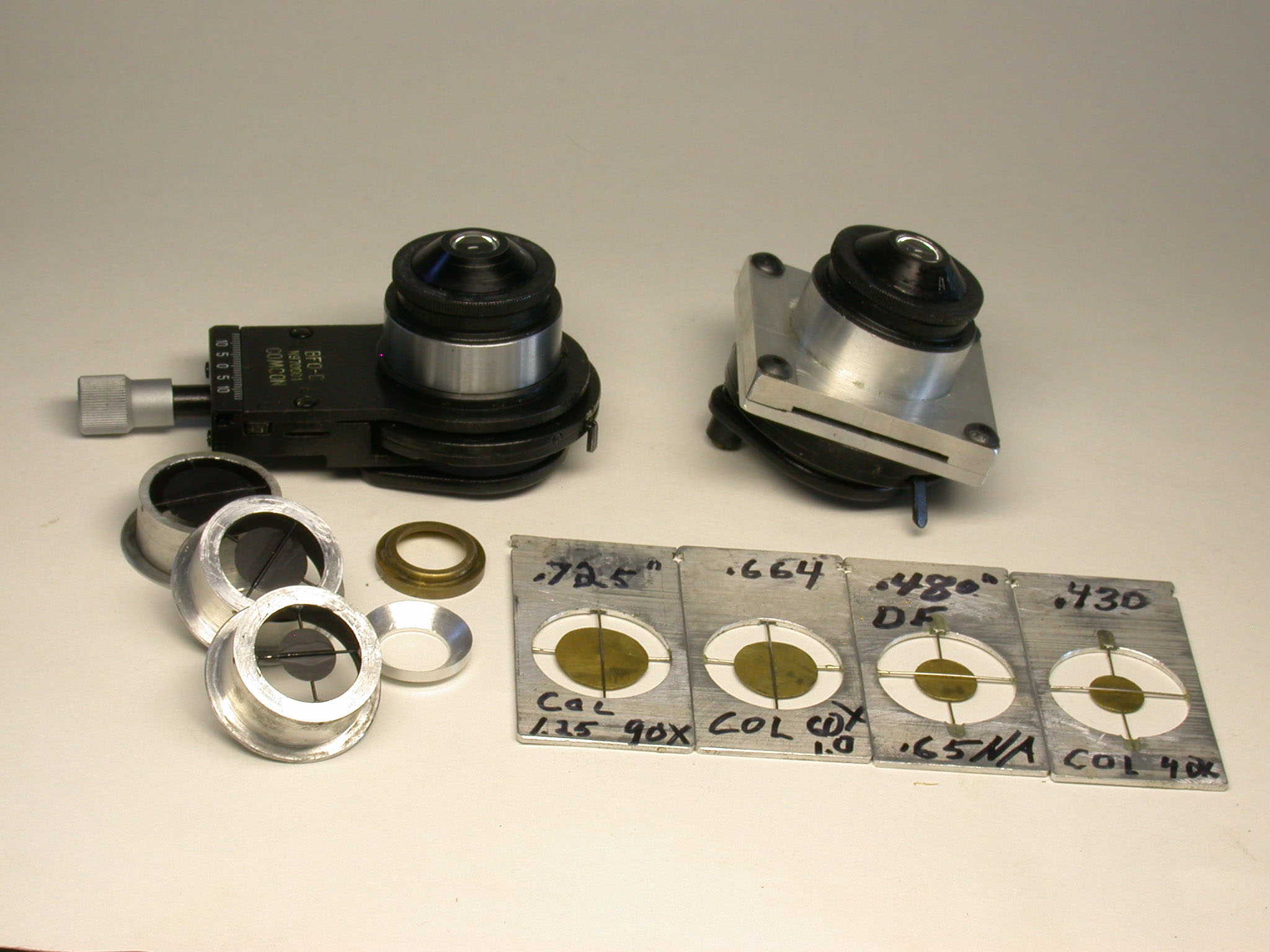
Fig. 4 (click image for master)
Figure 4 shows both of my 1.40 NA condensers. The condenser on the right uses the LOMO optic with a base I designed and made. This was the condenser used in this study with LED illumination and the fluid retention cap made from aluminum. The base of this condenser accepts the slider-mounted stops shown in this figure. The stops are made from brass shim stock by using a compass to scribe the circle followed by scissors cutting and filing to the scribed line. The unmodified LOMO condenser on the left is shown with stops which insert into its bottom. This unmodified condenser was used with the brass fluid retention ring and immersion oil filling the 1.1 mm gap to the bottom of the slide to obtain the darkfield image of chrysotile shown in Figure 5 using the 1.25 NA 90X objective. (The index of refraction of the mountant was 1.55.) The darkfield stop was inserted at the end of the fiber-optic light source, my initial method of obtaining darkfield with the LOMO condenser.
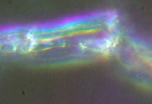
Fig. 5
The vertical illuminator was left installed, but its flashlight turned off, when the photomicrograph in Figure 6 of Amphipleura pellucida, with resolved striae, was recorded with transmitted COL. The field diaphragm could not be resolved, so Koehler illumination was not established. Figure 7 shows the diatom striae resolved with reflected COL. The field imaged field diaphragm was closed to confine the illumination to the 'Ap' diatom as shown in Figure 8. Obtaining adequate illumination for reflected light illumination of the diatom was a problem until I tried a LED Laser P6 shown in Figure 9. This is the brightest flashlight of the three shown, but required the addition of a 15mm diameter 15mm focal length lens against the fiber-optic light-guide shown in Figure 9. The one problem I have had with LED flashlights is leaving the batteries in them for storage and having corrosion from a leaking battery ruin one of them.
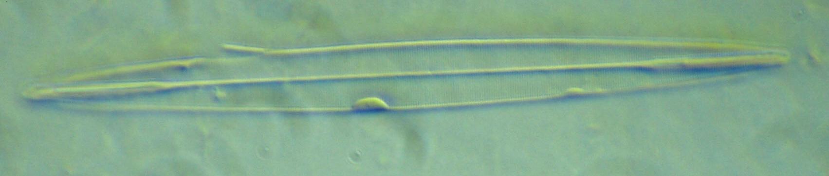
Fig. 6 (click image for master)
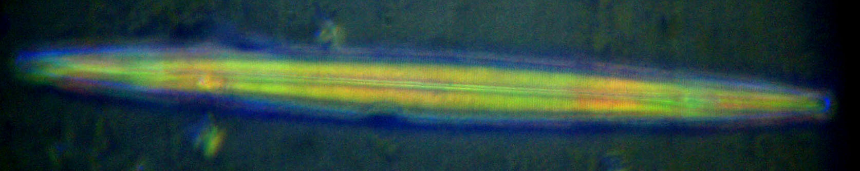
Fig. 7 (click image for master)
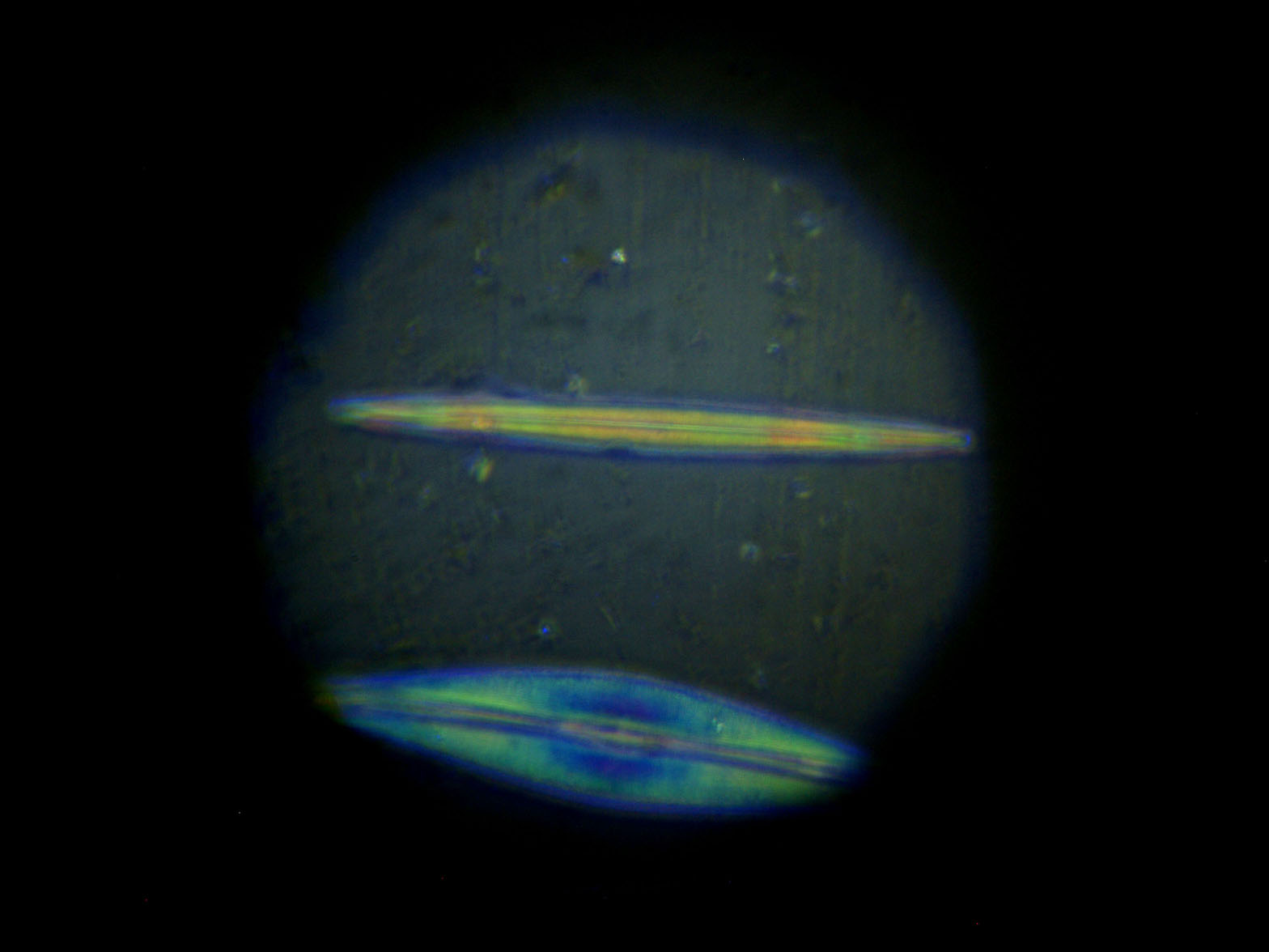
Fig. 8 (click image for master)
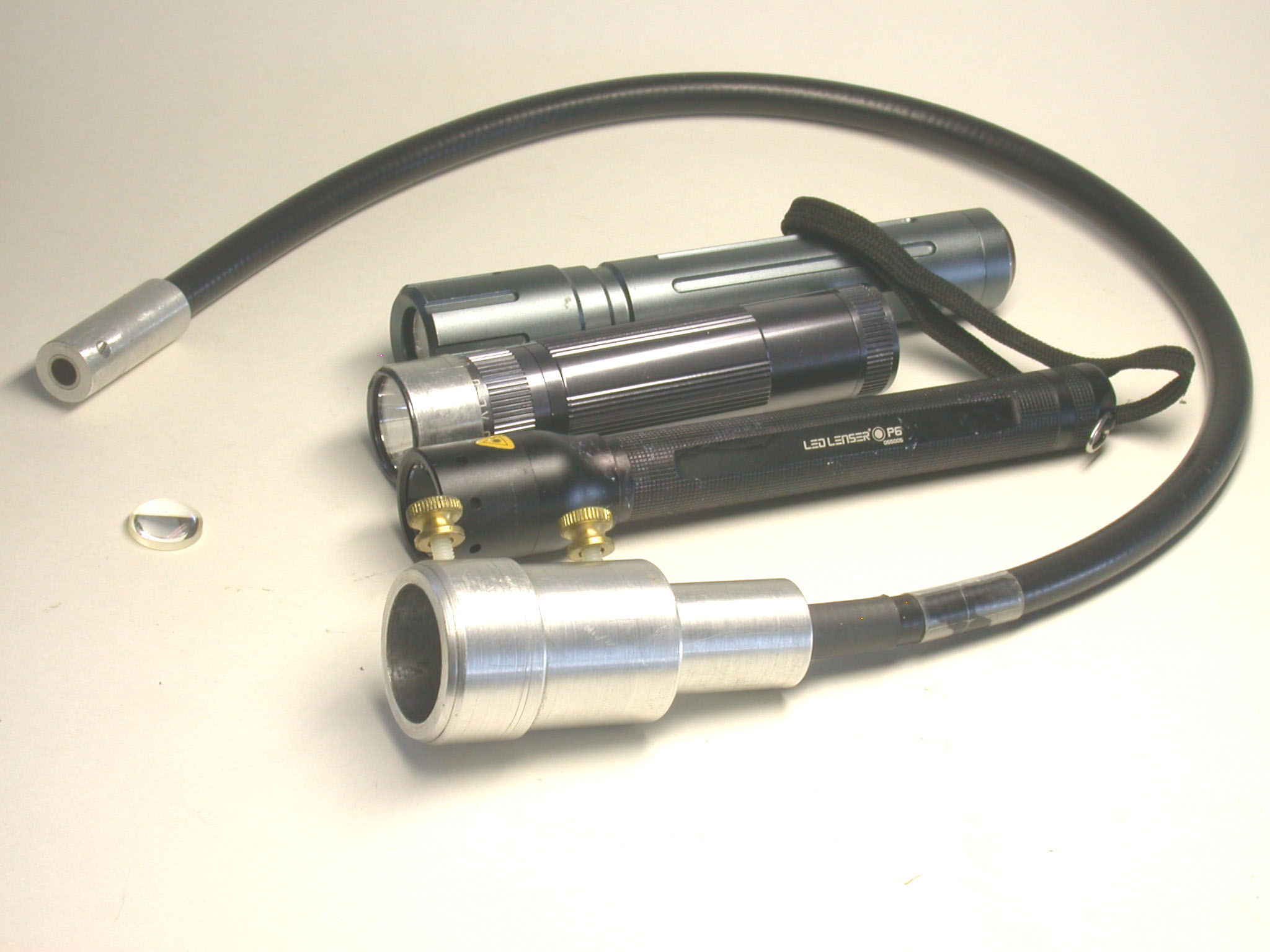
Fig. 9 (click image for master)
Comments to the author are welcomed.
Microscopy UK Front
Page
Micscape
Magazine
Article
Library
Published in the September 2012 edition of Micscape Magazine.
Please report any Web problems or offer general comments to the Micscape Editor .
Micscape is the on-line monthly magazine of the Microscopy UK website at Microscopy-UK .
© Onview.net Ltd, Microscopy-UK, and all contributors 1995 onwards. All rights reserved. Main site is at www.microscopy-uk.org.uk .