 |
An almost free low power microscope… If you have a not so cheap biological microscope
|
|
|
| |
An almost free low power microscope… If you have a not so cheap biological microscope
|
|
|
| All pictures recorded at 640 x 480 px and trimmed or reduced as needed to be included in the article. Objects for the macros were illuminated only with a little handheld torch. Only one shot. None of the pictures were multi-shot amalgamations. |
|
Preliminaries.
- Well, do you
have a biological microscope with
built-in illumination?
Equipped with
4x, 10x, and perhaps 40x objectives plus at least a 10x eyepiece? I say “so-called”, because if you do not have very high quality, highly prized equipment, it is most improbable that your illuminator has a focusable frontal lens, and an iris lamp diaphragm (field diaphragm). Both requisites are needed, according to good theory and practice, to install “real” Köhler illumination. (See the articles by F. Sterrenburg.) Well, as all this has embarrassed me, I managed to improve the performance of my poor bug.
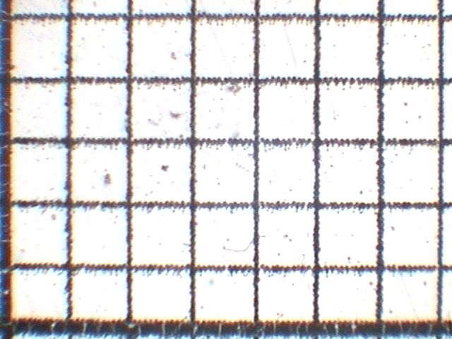
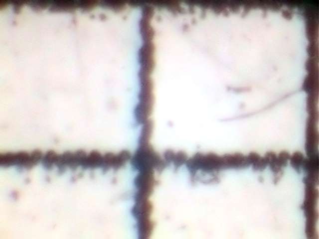
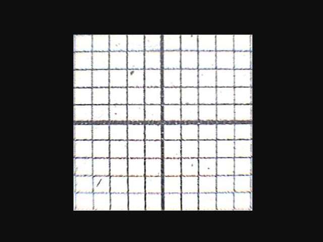
I
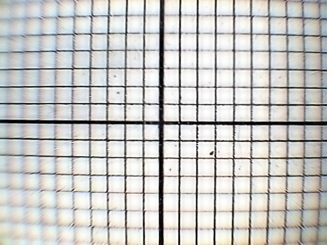
now changed to a transparent 1 mm square grid printed on acetate and
took a
picture at each power (see figs. 4 to 6).
Now, allow me a little disquisition. Have you tried at some time to select material
from a sample with a micropipette, using the low power of
your microscope?
If you don’t have a stereoscope,
certainly you will try. What a mess, don't you agree? First of all, in
a
normal
modern microscope you have one 4x as your lowest power objective, and
with
your 10x
eyepiece, you must work at a power no less than 40x, with a working
distance
between
the objective and the slide of more or less 12-13 mm. Second and worst,
you
must work in the inverse direction. You know that your microscope
inverts
the image.
This is why you put your slides “as seen facing to the back of the
microscope”. So, at high power and with an inverted image
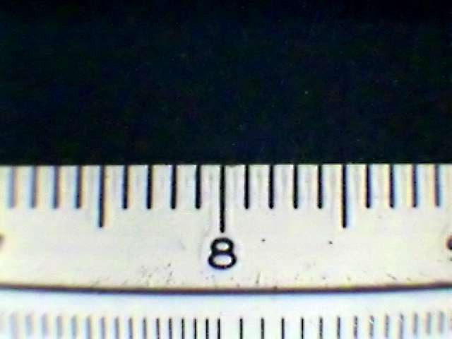
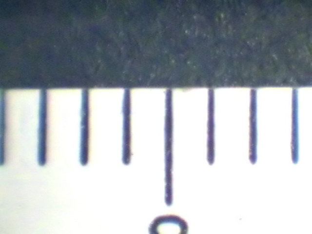
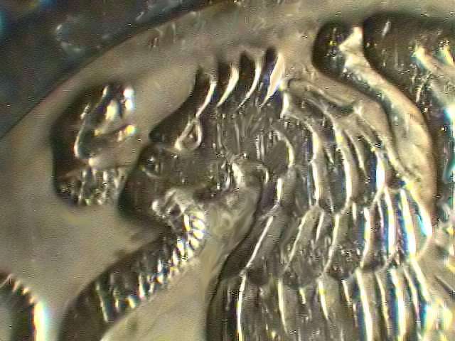
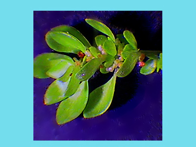
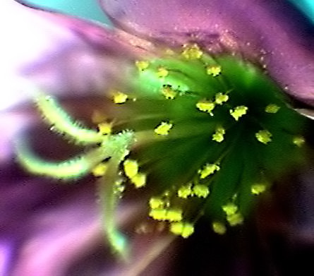
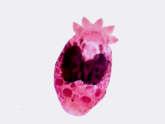
it is very difficult to make the correct manual actions. And now…a mostly unexpected and really wonderful phenomenon is that the rule I see was the right way round. Right! (Fig. 1)The condenser acted as an invertor and projected a right image through the microscope!!! Now, I have a digital camera integrated into my micro', and I can capture the image of the field of view on my computer’s screen. Measuring the images with any one of the methods discussed in my earlier MICSCAPE articles, I calculated 12x, 23x and 85x for the three objectives. (Note: the magnification depends heavily on the vertical position of the subject, if you put the object 1 cm higher you still can focus on it but at a lesser magnification.) I have received a gift: a low power microscope to complete the scale of useful magnifications of the biological micro' (if you have a system like mine). Mine has now 12x, 23x, 40x, 85x, 100x, 400x and as I have a 100x OI, 1000x. And for the three bold figures a long, long, working distance between the condenser and the lens of the built-in lamp. Any way due to resolution problems (at least with my microscope) I consider that the useful magnifications are only the 12x and the 23x. Exactly what you (and I) may have needed in order to do an occasional macro study, dissection, or comparison between some small objects. Yes, yes, my friends, I also see the distortion! Wait two minutes, please! But it is an inherent consequence of Köhler illumination set up.
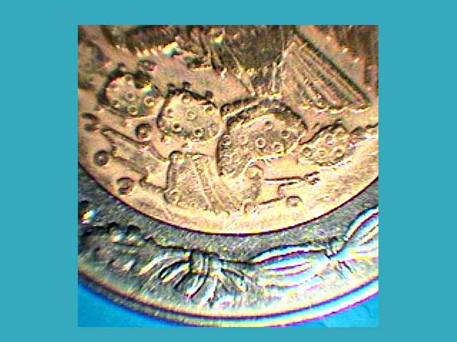
Of course what I do
not have is a dedicated stereomicroscope; the system does not
have the
stereo view capability, nor the depth of field of the stereo. And the
4x, even being a planachromatic that gives a neatly
plan field of view with a diameter of 4.0 mm in normal usage, gives an
image
with a clear vignetting effect that limits the “in focus” section of
the image
to a square of 10 x 10 mm. accounting only for roughly 50% of the total
width of
the field of view of 20 mm. This must be my working field of view and a
mask must be made to apply over the field lens to shut off the out
of
focus parts of the image. For the pictures, the solution is the same: one
mask *.ctp draw
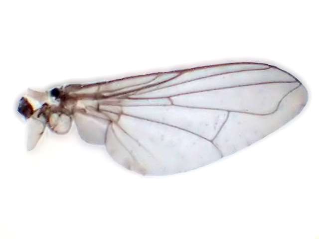
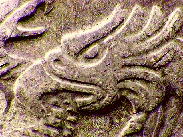
in PhotoPaint with a transparent center square. The 10x and 40x that embrace a smaller field of view don’t show this defect. The lines over the entire field of view (both visual and camera) are almost orthogonal (figs. 3 and 4). The problem with the 4x is important only when you try to make a photomicrograph. When working for sampling or dissecting you can use a slightly bigger field than 10 x 10 mm because our brain and the micro focusing device makes the necessary corrections. As the subjects are normally of a certain depth and with many planes, the aberration is less than a concern. However, and in spite of this, I (perhaps we) now have the opportunity to take some macros (little flowers, postal stamps, little coins, (fig 6, 7) sand… I leave you to complete the list) or make the dissection of the mouth parts of an insect, or the legs of a copepod … (if you have the appropriate tools and your hands have the needed ability). Opaque objects- These are the chosen subjects for this “microscope”. The quality of the recorded images, I think, would depend on the quality of the camera you use and of the lighting system, and if you wish to capture the depth of the object, you must do multiple focusing and shots, to recombine them afterwards with some program such as CombineZ or Image J (both are freeware) or the similar commodity of PaintShop Pro (Jasc’s shareware photo processor) and of other photo processors.
Also the
definition or resolution of the image is impaired compared with the
normal
microscope image. Try the iris aperture
diaphragm as a very modest
depth
of focus control. Think of the condenser as now being your objective.
Try
diffuse light, with the 4x objective. Be prepared to supply lots of
light for
your 10x, and specially to your 40x if you can use yours. Also, use a
soft type
of illumination.
The best
setup is possibly a combination of 3 or 4 white, high intensity, LED’s
(6800 to
8000 candles) regulated with individual switches and potentiometers to
allow a
careful balance of the light.
Viewing
and photographing transparent subjects.- If you don’t use opaque stops the normal light
of your microscope can shine through the transparent objects you put on
your
stage.
You
could use the transmitted illumination
possibilities to view and photograph transparent subjects, even
prepared
slides, which are suitable for normal microscopy observations, at lower
or
intermediate powers. However, the system (in my set up) is not very
good (for
the moment, at least). The definition is not sharp enough to fulfill my
expectations. I could not implement a diaphragm system to control the
cone
(the aperture) of the transmitted light.
Trying the 40x
and 100x.- I suspected that if I could give enough light to
my 100x, without
overheating the subjects and the system, making immersion between the
frontal
lens of the condenser and the objective through an intermediary slide
(remember
that you must put an oil drop over the condenser top lens, apply a
plain and
clean slide and put another oil drop between the slide and the
objective) must
allow me to recover some image. I tried it. I had a poor 100x image (I
get this
more easily and with much better resolution with the “normal style” of
my
microscope using the 10x objective and the 10 x eyepiece) I do not
think I was
supposed to use the macro 100x feature. Even the 85x (x40 obj.) has not
enough
contrast and definition to warrant its use, especially because defects
are worse
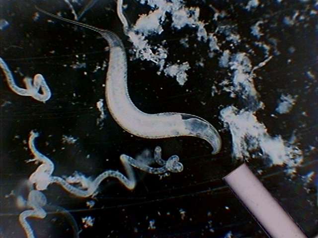
in transmitted light. But try, with some subjects it works. At more or
less 20x (10x objective) the instrument becomes a useful selection
device. Fig.
6 shows the device at work, with the sample in a little Petri dish,
over a
black velvet background, illuminated by an incandescent light, and with
a
nematode about to be picked up with a micropipette.
Older
microscopes are also useful Even with the very old achromatic optic of the Koritska, the focus was very clear on objects placed on the table, between the sturdy legs, or even on a platform supported over the square section legs. An exterior desk lamp with a 50W, internally mirrored bulb, gives enough light to work easily. Protecting the lenses from reflections I made a cylinder of black cardboard that fits over the frontal lens of the condenser and embraces the objective. This totally corrected the problem. I will make the same adjustment on my new microscope. With the oldest microscopes with straight tubes, you have the additional problem of working with the microscope vertical, which is not very comfortable, really. What is lost in the old microscopes is the capacity to have transparent objects being lit from the underside. However, with a little brain work most of you can fix the problem. Conclusions But I remember the times in which I only could manage to buy my second-hand Koritska, and I could not afford to acquire one binocular microscope no matter the cheap it could be. Over 40 years I have the Koritska making a fine work for me, but unfortunately I never suspected that I could had use it as a modest but useful low power microscope. I think that this article could aid perhaps at some of the so called “silent majority of microscopists” that has modest equipment and budget, and even has not camera, but occasionally need to do some work at less than 40 x. Refining the instrument
The optical resolution is better than the pictures shown. So if you are willing to implement some working version of the above, I suggest that you: 1) Make a working stage, with rigid cardboard, cutting one central hole to admit the rim of the lamp (if your microscope has a built in illuminator), and lateral supports to give it stability and allow a resting surface to your arms. This would be not necessary with many old, “mirrored” microscopes you can work on the table, between the microscope feet. 2)
Arrange
an illumination system, best with 3
or 4 white LED’s. 3)
Cut
cardboard stops to put over the
frontal field lens. If you do, make some of them colored or textured
to give
alternative backgrounds to your subjects. 4)
Taking
out the stops allows transmitted illumination.
Have a cardboard diaphragm with a
hole of more or less the size of the orthogonal field you have
determined, and
a glass plate to put over the cardboard stage for a more easy
manipulation.
Close the aperture diaphragm (the condenser’s one) and graduate the
intensity
of the microscope lamp. Please!
If
you make some experiments about this system, let me know of your
results! I
would be glad of having notices about the behavior of microscopes of
different
technical levels, and especially with other kinds of condenser and
optics. |
Please report any Web problems or offer general comments to the Micscape Editor.
Micscape is the on-line monthly
magazine of the Microscopy
UK web
site at Microscopy-UK