USE of the LOGITECH QUICKCAM PRO 9000
for photomicrography
History of a near-failure, or a semi-success
Walter Dioni
Cancún, México
INTRODUCTION
This article is NOT written for
those with good quality photomicrography devices, already installed and working
properly. The audience I address are those with a limited budget, and
very little knowledge of the subject, who want to try, like me, to install an
inexpensive (that is to say, within their budget) but reliable option.
All approaches I found to this problem always explain, for the described camera,
an already working installation, and usually a successful one. Few people
talk about the reasons underlying the options used, and it is difficult to find
an account of why the other considered options were discarded... and which
failures were suffered. And this is, from my point of view, what we really
try to find, those who have a problem and a guide to aid us to prevent or minimize
such failures.
This is a chronicle of the adventure in which I embarked, wanting to improve my
photomicrography capacities. I knew little about the theme, to begin with, and
I still have much knowledge to acquire. But I hope the data that I bring together here
is not too wrong, and can provide guidance to some other beginner who also
aims to investigate the capabilities of a webcam.
I think the article could really
seem excessive. And somewhat naive. Anyone of average intelligence
can imagine in advance the result of some of the tests I do.
But I feel that it is this visual and eyewitness testimony, which really
interests me to share.
This presentation is organized
into 3 parts. The first one explains my problem, and my preliminary researches
to decide which particular camera to test.
The second shows test samples,
with the camera for photomicrography and the results (favourable or not)
that I have achieved when working in brightfield.
The third looks at the results I
got (favorable or not) trying special techniques such as oblique illumination, dark
field illumination, episcopy, Rheinberg illumination, polarized light, and
several contrast techniques which give more or less acceptable results when
using my DC3 camera.
Unfortunately I can not provide
data on the use of this camera with phase contrast, because I do not have the
right equipment.
Maybe that
with my obsession for this article, I shall exceed the limit of patience of my readers.
But I'll never get to know this, if I do not share it.
My Current Equipment
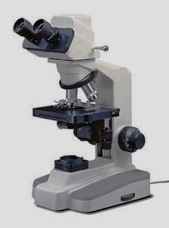
I have a National Optical
microscope with MOTIC camera and planachromatic objectives. The DC3 camera
built into my microscope has a sensor that actually produces images of only
0.08 Mpx (320 x 240px). An internal resizing program (probably with bicubic
algorithm, or better) and delivers acceptable images of 0.3 Mpx (640 x 480px)
therefore at a size four times bigger than the original.
It is included in the head of the
microscope and cannot be removed, nor modified.
With the microscope I was given a superb
management program (Motic Image Plus 2000 v.1.3), which
allows the taking of still images, and videos from 320x240px to 30 fps (frames per second), in a
very simple exercise. It also allows image capture in rapid succession manually (I can usually
capture up to 5-6 frames per minute), or automatically. The camera is mounted in
a way that captures the best rectangle inscribed in the field visible through
the eyepieces.
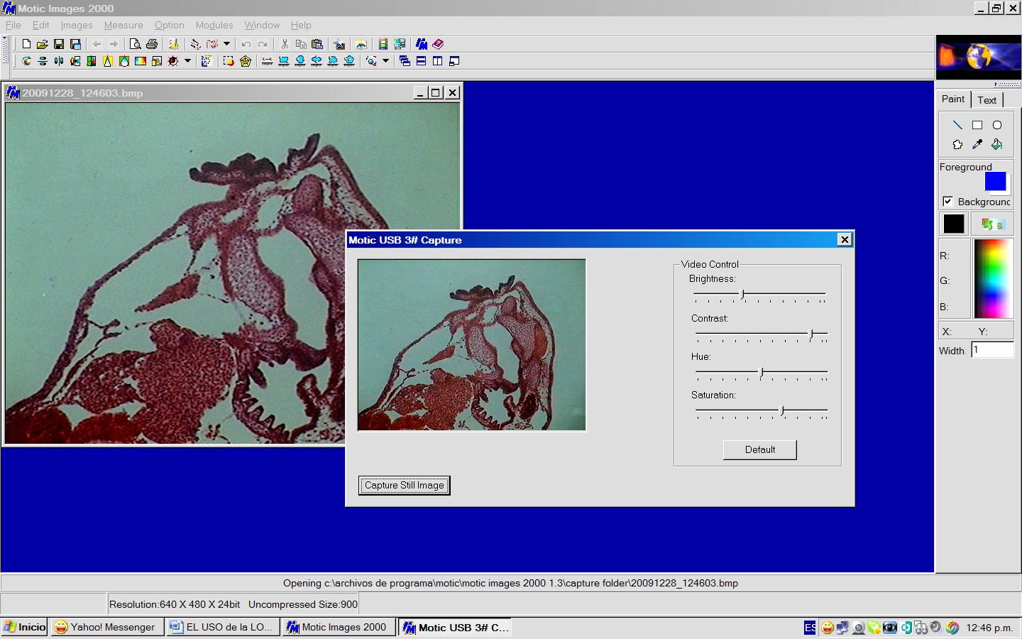
An overview of the screen from the Motic
2000 v 1.3 program with the capture screen displayed. A click on the button
"Capture still image" displays a frame with an image of 640x480,
behind the screen capture (showing image of a histological section of a tadpole
4 mm long, captured though 10x objective).
The height of the computer screen is 25.5 cm with a width of 41 cm. The display
capture screen (320 x 240 px) is 98 x 68 mm. The Capture Viewer has as its main
function the electronic adjustment of the image, because the capture itself can
be simply done while viewing the subject directly through the binoculars. The
camera is parfocalizable very easily.
The microscope is equipped with 4x, 10x,
40x and 100xOI planachromatic objectives and a "pre-centered" Abbe condenser
1.25 N.A. Lighting is provided with a 12V 20W lamp that generally is somewhat insufficient for the 100x objective in oil immersion (varies
according to the subjects). Although according to the
manufacturers it has a preset Köhler illumination, the existence of a thin ground
glass diffuser filter between the lamp and the front lens of the illuminator
allows only "critical lighting", or "poor mans Köhler" as
the best possible light style.
Eight years ago this camera was justified,
because although it was advertised as a
"research microscope" it was in fact designed as a microscope for an
advanced student of a science faculty, and at that time the VGA format was very
common on computer monitors. The reasoning that led to the design of this
microscope was apparently impeccable: the integrated camera will avoid all the
problems of adapting a consumer camera, the sensor is fully protected, and
located in the right place to record the largest rectangle inscribed in the
field of view, the camera provided the ability to monitor the microscopic
picture live on the computer screen.
This was easily parfocalizable, and,
providing the microscope with an additional output for TV, and management
software more than acceptable (that even now remains of high quality), facilitated
the observation and taking pictures in quick succession, or even short videos
while viewing directly by the eyepieces.... It wasnt taken into account (I
think that few people currently did, and I of course did not) the fast and
explosive development of digital photography and the race towards offering more
and more megapixels (which is not finished yet) and that soon made the VGA
format obsolete. Although these models are still selling, most of the MOTIC
microscopes of this kind are currently trinoculars. MOTIC now manufactures
independent cameras: from the 1.3 Mpx Moticam 1000 (carefully reviewed by D.
Walker at MICSCAPE), to 5 Mpx professional cameras.
http://www.microscopy-uk.org.uk/mag/artmar05/dwmoticam.html
More megapixels (despite the table
included below, and all assertions to the contrary made repeatedly) represent
better resolved images at digital level. Anyone can verify that this is
extremely important for a good interpretation of the subject. I believe that these two images will make the
point clear enough:
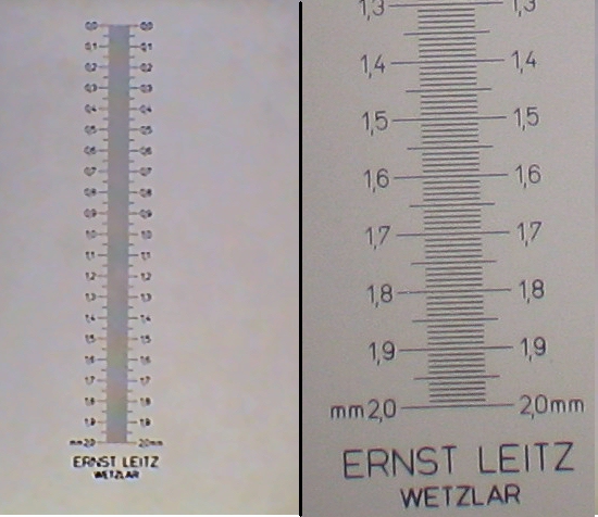
4x Objective - two micrometer images respectively taken with the DC-3 (left) and a SX100is Canon of 8 Mpx. The DC·3 is the complete image. Both pictures trimmed from the originals
It is also true that every time that I
submitted to others judgement, pictures displayed at the capture size, or others
electronically enlarged; the largest (within reasonable limits of course)
always got a better appraisal. (See below for Logitech images at different
sizes).
To improve the capture size I decided to try adapting an external camera, supported on one tube of the binocular head.
According to the next table, a 1.3 Mpx
camera is sufficient for the whole range of my objectives.
TABLE
OF THE MINIMUM PIXELS AND REQUIRED NA (planachromatic objectives)
Objective N.A. Recommended image size
4x 0.10 1364 x 909 - 1.24 Mpx
10x
0.25 1364 x 909 -
1.24 Mpx
40x 0.65 886 x 591 - 0.52 Mpx
100 x 1.25
665 x 436 - 0.29 MPx
Note: The calculation of this type of table depends on many factors (the NA and type of the used objectives, achromatic, planachromatic, planapochromatic), the number of photodiodes (2 or 3 e.g.) assigned to register each resolved point of the subject, sensor type (monochrome, colour and sensor type) the value of the relay lens reduction, if it is used, and also whether the photos are to be for screen use, published on the Web, or if they are to be printed, in which case there is of course an important interaction between the quality of the digital photo, the quality of the printer, and the size to which we intend to print the image.) But the important thing is that all calculations agree to allocate a higher demand in the quality of the sensor, and the number of photo diodes required, to low power objectives, with a ratio of 3 or 4 to 1 between the lower to bigger magnifications.
The ease of capture and image quality, depend of course on the chosen camera. From my
particular point of view I was seeking a camera that has these 13
characteristics.
a. Small size and light weight to allow an easy adaptation to a binocular head
tube .*
b. Sensor of good quality .*
c. Image Capture 1.3 Mpx at least, according to the table above (2, 3 or Better
4 Mpx, to be preferred)
d. High capture speed, in order to photograph moving subjects
e. Capturing blank backgrounds for correcting background dirt *
f. Monitoring of the screen image in real time *
g. Adjust lighting, color, contrast and white balance *
h. Large video frame (monitor) screen for easy composition and focus
i. Electronic capture to eliminate vibrations .*
j. Manual sequential captures, as fast as possible
k. Video capture as fast as possible
l. Ability to apply darkfield, Rheinberg, oblique illumination and polarized
light techniques
m. Ability to capture stacks to use in CombineZ * or similar software
Cameras
similar to these would meet these requirements:
Special cameras for photomicrography
Motic
MC 2000 2.0 Mpx
U$ 799
Motic MC 1000 1.3 Mpx
U$ 654
(The DC 3 integrated camera is only sold
in the DC3-163 digital microscope system)
Swift 1.3
Mpx U$ 499
MicroscopeNet (eBay) 1.3 Mpx U$
189
0.3
Mpx U$ 100
Bresser 0.3 Mpx U$
130
1.3
Mpx U$ 324
Webcams, better suited for
photomicrography
Phillips SCP1300NC 1.3
Mpx U$ 156
Philips SFP6500/00 2.0
Mpx U$ 128
Logitech Quick Cam Pro 9000 2.0
Mpx U$ 100 cost.2009
Logitech C-950 2.0
Mpx U$ 100 cost 2009
Logitech Quick Cam Pro 9000 2.0
Mpx U$ 90 (my cost)
Note:
Apart from the price of my Logitech, which is the price at which I acquired it in
Dec. 2008, the rest are prices as for December 2009, obtained from online
offers.
For all these cameras I would have to add shipping costs to Mexico that are
usually around U$ 28-30 if imported from the United States, and insurance,
because of the many risks of the transport. I do not know the price from
Europe. Usually, in Mexico, customs also collects taxes on the importation of
technical instruments.
Why from the list I selected
the Logitech QuickCam Pro 9000
1 Because some leading amateur microscopists use it and
even post very acceptable videos on YouTube.
Many posts
by users of this camera can be read in the Messages of the MICROSCOPE GROUP
2 Because it meets 9 and with certain conditions 10 of the 13 requirements for
the best camera. The conditions not met, or fulfilled only in a limited way,
are:
a.Capture of images at least at 1.3 Mpx according
to the above table. According to their current operating conditions (see
below) it only captures images of 0.8 Mpx. (roughly 60% of desired)
b. High speed capture, to
photograph moving subjects. As will be seen below, 2.0 Mpx images (0.8
real) require 1 second to be recorded.
c. Ability to apply darkfield and Rheinberg techniques. The tests so far suggest that it is
possible to use oblique
illumination and polarized
light, but dark-field images
are not very good (much
"background noise").
3 Because it has a Zeiss Tessar lens with 5 elements.
4 Because it has a 2 Mpx sensor,
advertised as providing high quality images
5 Because it has a program that has
control of the lighting intensity, and which I thought could help to record
better images at high magnification (with limited lighting)
6 Because it is totally manageable
with the computer
7 Because the images monitor screen is
large (20 x 23 cm on my monitor)
9 Because it is very easy to
disassemble and only weighs 30 g
10 Because it costs me $90 and
was available in Cancun, while the European Philips are not available here, and
are more expensive.
11 Because it cost me $0.50 to fit it
to the microscope.
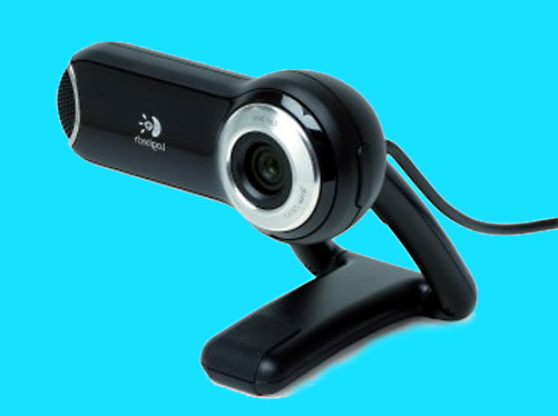
ADAPTATION TO THE MICROSCOPE
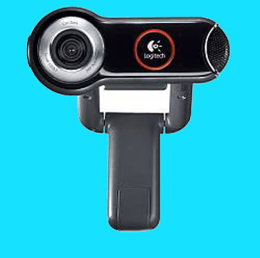
The first
task to properly adjust this camera to a microscope, is to remove the brackets that allow its attachment to the computer screen, or support it over the desktop.
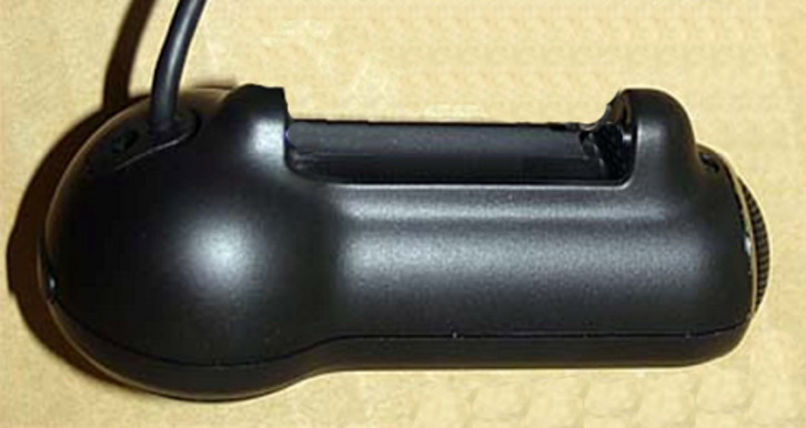
These are pictures of the entire camera.
|
|
|
In an article by Gary
Honis (http://ghonis2.ho8.com/Pro9000a.html)
on adapting the camera to a telescope, he illustrated step by step
instructions not only to dismantle the camera, but to transform it into another to be
attached directly to a telescope .... or even a microscope, of course.
The author also describes and illustrates very effectively with the camera
itself the consequence of the inevitable removing of the Infra Red (IR) included
filter, and the need for replacement, as will be seen below.
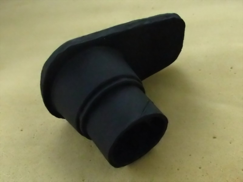
This is the image of the camera as it was after I removed what I dont need.
The connection to the
CPU uses a USB 2 port.
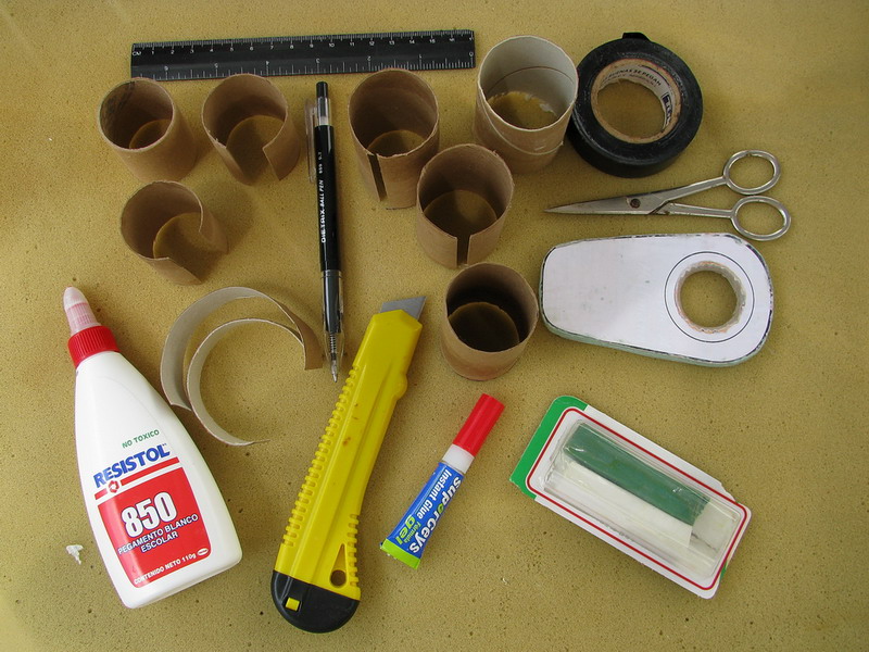
You only need to install the camera on a support that fixes it properly over
the eyepiece. This is the one I use.
The preparation of
the adapter needed the materials below and I believe that the description of the
process is implicit. A ruler, a choice of cardboard tubes, cutting and gluing materials is
almost all that is needed.
There are two methods that work with two well defined types of camera:
1 - Those with a fixed front lens, immovable, with which you can only use the
system known as "afocal", using the camera and microscope as they are,
or at most changing the camera lens. What sort of pictures can be
taken with this system?
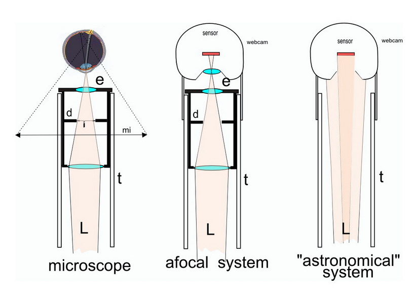
As seen at left, the eye views through the front lens of the eyepiece (e), the image ( i ) projected by the microscope objective in
the plane of the eyepiece stop (d) and the brain recognizes the magnified image (mi) - L, light path - t, tube of the microscope
The afocal system uses only part of the sensor. The "astronomical" system uses only part of the field of view
The system I call "astronomical" because of its extensive use among
amateur astronomers, is one that only uses the microscope objective, and
discards the microscope eyepiece and the lens of the camera.
|
|
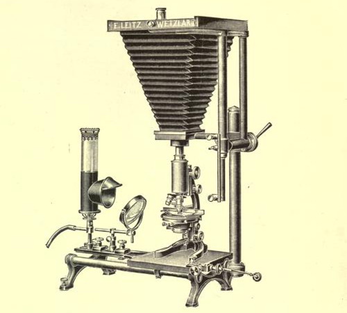
This was indeed the method we used for amateur
microscopy in about the 1950s or 60s, adding to the end of the tube of the microscope, without
eyepiece, a bellows without lens, with a cone or a hollow pyramid with
height proportional to the desired magnification, and using at the end a
sensitive element (sensitized glass plates, silver bromide paper, or 35mm film).
If the sensor is placed 25 cm from the exit pupil
the magnification of the photo corresponded exactly to the nominal magnification
of the microscope. The amateurs of the twentieth century like myself often used
cardboard cones, at the end of which was glued a wood and glass frame that we
used to make prints on sensitized paper. Instead of the usual sandwich "glass-negative-sensitive paper, bare bromide
paper was placed in the frame and we exposed it to the light projected by the objective
of the microscope. The image was later
chemically reversed. Rigorously working in a darkroom of course. |
As we speak of discarding the lens of the webcam we must make it clear that this is not a trivial action, and that we must be ready to counteract its effects. Read the APPENDIX IV
In France the Philips webcams were used for years. (Until recently they were of
0.5 Mpx, and since a couple of years ago of 1.3 Mpx. Now they have 2.0 Mpx.
Apparently sensors previously used were CCD, but the maker's specifications indicates that now they are using CMOS sensors). Webcams
were used by adapting the method used by amateur astronomers: camera without lens, microscope without ocular.
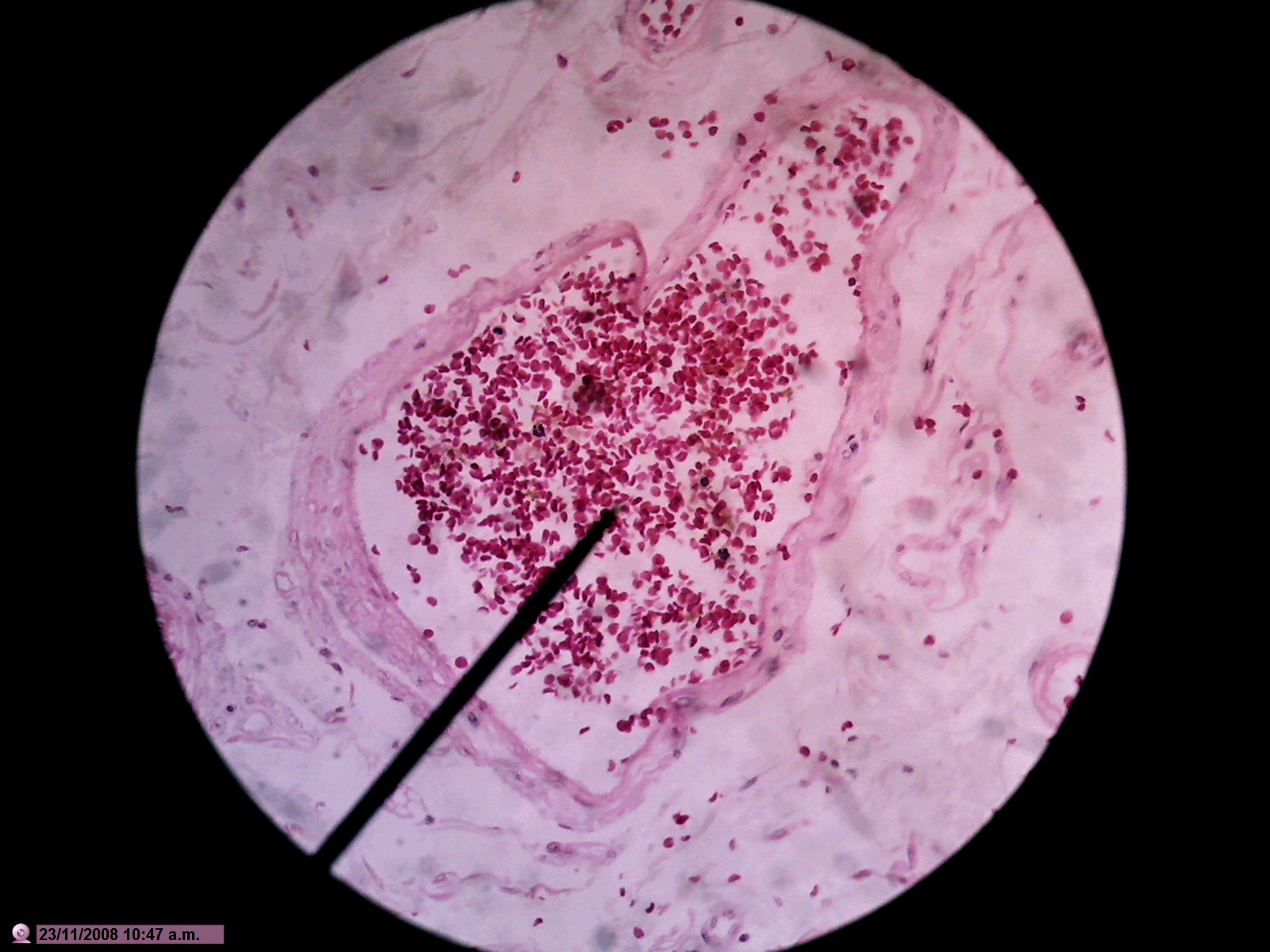
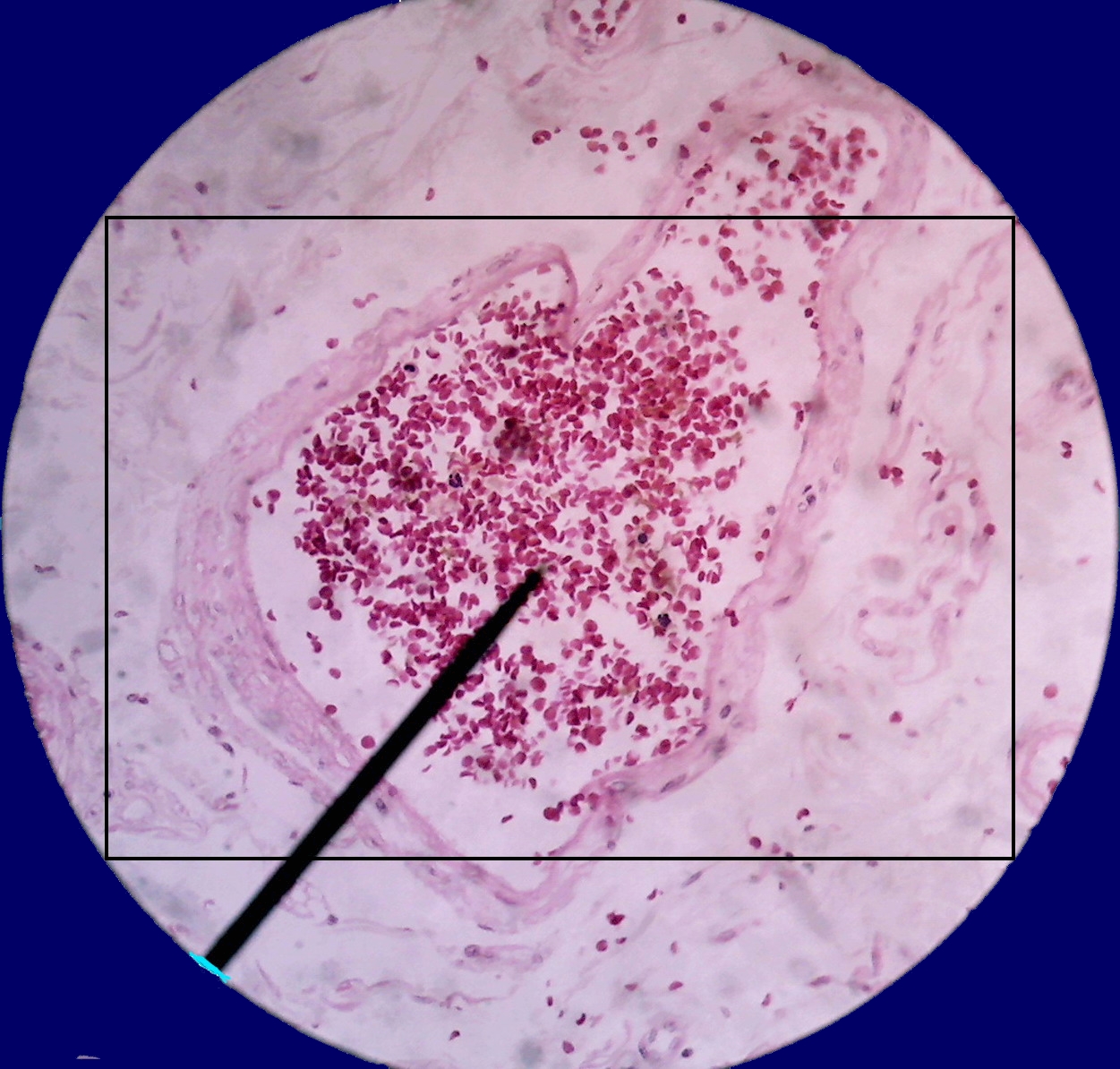
Although
through their eyepieces the microscopist would see the complete the picture above,
the following would be an example that mimics
the part of the field that the camera would record.
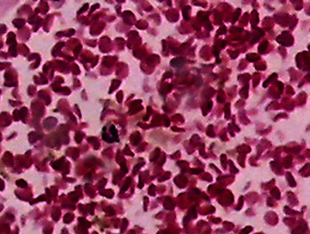
People involved in higher invertebrates research, or histology, surely want to have greater
field of view coverage. These people are more interested in
It is based on simply
applying the camera to the eyepiece of the microscope, adjusting it properly to
the exit pupil, and to be satisfied to record the total field of view at the magnification allowed by the sensor coverage.
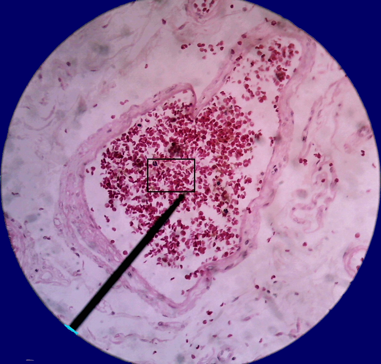
This is an example of an image obtained under these conditions by the Logitech
9000.
The black rectangle is actually the recorded image of the full sensor. The
central circle is the area of the sensor actually used. This effect is
usually called "vignetting".
Full sensor Rectangle: Image 1600 x 1200
px = 1.92 (2.0) Mpx
Full Circle
(without zoom): 0.8 Mpx (only 40% of
the sensor, but 10 times greater than that recorded by the DC3)
Maximum allowable cut with ratio 1:1.3:
800px x 600px = 0.48 Mpx = 24% (relation to DC3 = 0.48/0.08 = 6 times)
Cut made in scale 1:1.6 ratio: 860 x
513 = 0.44 MPx = 22% (5.5 fold increase)
Maximum square inscribed in the circle:
710 x 710 = 0.50 MPx = 25% (6.25 times higher)
Of course the ideal solution is this one.
SOLUTIONS USED - Faced with this
reality microscopists have opted for some effective solutions.
To cover the sensor completely I need to replace the wide angle lens of the
Logitech which have a focus of 3.7 mm, by one of 8 or 9 mm focal length,
according to calculations that Charles Krebs kindly communicated to me. This
means that I should provide it with a telephoto lens.
There are on the Web some addresses of suppliers of suitable
lenses. (Two recommended in the Forum MICROSCOPE are: www.sunnex.com and www.optekusa.com)
The lenses themselves are not too expensive (depending on their quality of
course). You can get up one for 20 to 40 dollars.
(http://ghonis2.ho8.com/Pro9000a.html)
and also
how to adjust the new replacement lens to the camera.
The new lens does its job by reducing the image field of view so that it only
covers all the photodiodes of the sensor, thus changing the geometry to fill the field.
Changing the microscope eyepiece -
The second solution is to acquire and use in the microscope a SWF (super wide field)
eyepiece with FN between 22 and 23 mm, and high relief point (eyepieces for
short-sighted eye) in order to project onto the sensor a larger-diameter
circle. These eyepieces are not easy to find, and are always very
expensive. (A 15x Olympus lens with FN 22 was offered at $170 on eBay)
and hardly provides a total solution.
Finally, if you dont buy an adapter there is the problem of preparing one at home,
to adapt the camera to the microscope. Solutions are also published on the
web. Relatively few are economic ones. The efficient Cavalue solution, for
example, not only provides a secure fixing of the camera in a working
position, but permits at any time to retrieve the same for normal use. But
the Lumicon adapter he uses, costs $50, over 50% of the price of my camera.
Others projects, based on PVC, or metal home designs, may have a favorable balance.
But involve having tools that not everyone has. Perhaps my solution is the most
economical, while being effective.
Camera + teleobjective + highpoint eyepiece + Lumicon adapter
90 dls 30 dls 170 dls 50 dls total with eyepiece 340 dls
without eyepiece 170 dls
Add the custom and
insurance fees if the material must be imported. Check prices for cameras
with 2.0 and 1.3 Mpx in the table above. There are 1.3 Mpx cameras between
130 and 320 dls
|
A summary of my
situation, after all this long analysis is:
My Canon A300 can by no means be successfully adapted, mainly due to its
turn-on system which involves a difficult to operate, manually slide
protection, for its lens. But I did buy a Logitech for $90, to undergo adaptation. for not to have to buy or import not matter what telephoto lenses, or
eyepieces, or IR filters, or adapters of any kind. |
To install the Logitech in these conditions was simple; it only weighs 30
g. and creates no tension on the head of the microscope.
Thus, my microscope is now equipped with the 0.08 Mpx DC3, 0.3 Mpx digitally enhanced, that is still relatively useful,
and which is managed since December with Motic Images Plus 2.0 software. It is usable with the 10x objective, but
especially with the 40X and 100xOI objectives. And the Logitech, installed on one of the
binocular head tubes, for all objectives, with 0.8 real Mpx. For occasional shots of absolutely immobile objects, I use the Canon A300, which I can manually hold over
the eyepiece.
Go to the 2nd. of 3 parts (in March 2010 issue)
Acknowledgements
I wish
to acknowledge the kind assistance of D. Walker and
J-M Cavanihac, whose thoughtful suggestions allowed me to greatly improve the
presentation of this article.