LOMO Biolam Microscopes.
Notes on refurbishing the oblique condenser and condenser diaphragm.
The third in a series of LOMO Biolam microscope maintenance projects.
By Ian Walker. UK.
Introduction.
This is the third in a series of articles about refurbishment and maintenance of the popular LOMO Biolam series of microscopes. The first covered the use of special lubricating oils and greases from Nye together with overall dismantling tips on the microscope, the second covered rotating stages and now I cover refurbishment of the oblique condenser. The LOMO aplanatic oblique condenser is a high quality unit but has not escaped the Russian grease notorious for its viscous and sometimes damaging properties, more often than not somebody buying one secondhand may find it in varying degrees of seizure either rotationally or obliquely sometimes with the diaphragm damaged. The damage of the diaphragm usually comes from forcing the diaphragm control arm with the blades solid with grease, this distorts the blades and the brass pins jump out of their fixing holes with the possibility of irreparable damage to the blades either through the pins pulling out of the blade or blade distortion. Once the blades are distorted it is difficult for them to be used again since the material is a springy metal not dissimilar to that used in old clock springs, once distorted it doesn't easily return to its previous shape especially in the case of sharp creases caused by the blade doubling up on itself. Although describing the LOMO condenser the basic concepts should be the same for other condensers in terms of maintenance practices.
Note 1.
For details of the two previous maintenance articles on the LOMO microscope stand plus lubricants and suggested stockist's see the end of the article.
The condenser.
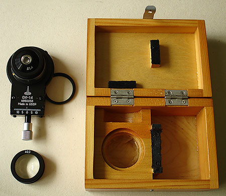
Fig 1.
LOMO oblique condenser with NA 1.4 optics screwed in position and swing-in filter tray.
The alternative low power lens is shown underneath and they all fit in a neat wooden box.
Suggested tools and lubricants.
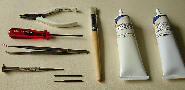
Fig 2.
Jewelers screwdrivers, tweezers, a stiff brush, high quality 'pin-nosed' pliers and greases.
A high quality jewelers screwdriver with a small selection of flat blades are almost essential for removing the various sized screws with some of the larger ones being removed with the larger screwdriver, no 'pozi' or Philips screws are used in the construction. The tweezers can be used for returning screws to their holes and laying the diaphragm blades in their correct positions after cleaning plus a choice of Nye lubricants are useful but not essential for re-lubricating after cleaning the sliding surfaces. For a lighter feel with less damping on the oblique control I recommend Nye 362HB which has the consistency of a light hand cream, this will give a very easy motion but no damping effect. Alternatively Nye 795A is a true damping grease which will give a slightly stiffer but well damped feel to the oblique control. It is not a necessity to use these lubricants, I have used tiny quantities of clean oil in the past on the sliding surfaces but the extra quality and feel of a good grease can't be over estimated. Once purchased these lube's will last a lifetime and are well worthwhile considering.
Cleaning solutions.
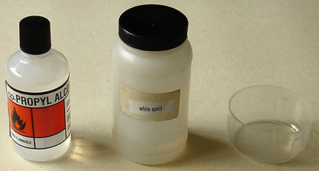
Fig 3.
Cleaning materials and a small receptacle for soaking the parts.
Isopropyl alcohol [a poorer alternative is methylated spirit] and white spirit are usually all that is needed for cleaning surfaces covered in hardened grease, the black gloss painted surfaces can be cleaned with a cloth dampened with warm water and a little washing up liquid. Not shown are some disposable kitchen towels which I find useful for removing excess grease and drying off the smaller parts after immersion, these can be cut into small squares to prevent wastage. I only recommend isopropyl for cleaning off parts already cleaned in the spirit like the brass and aluminium sliding surfaces I don't recommend rubbing the black painted surfaces as this can dull the finish and remove the white lettering. A modest receptacle like a very well cleaned used margarine tub or deep plastic lid can be used for immersing the smaller individual parts to soak, be careful if you use the plastic lids from spray cans they often have a little hole drilled in them allowing your cleaning fluid to leak out! In general the white spirit [or clean paraffin] will remove most grease especially with the smaller dismantled parts being soaked for some time, the use of a stiff brush as shown in Fig 2. will be useful to get into the teeth of the oblique gear assembly together with the smallest flat blade of a jewelers screwdriver to remove stubborn deposits. Do not be tempted to use any other solvents unless you are sure of their properties since some can be very damaging to the painted surfaces.
Note 2.
Some plastics are susceptible to softening and warping when white spirit is left too long in them, as always caution must be used with flammable materials especially the 99% pure isopropyl alcohol which has a low 'flash point', if possible keep a window open to prevent build up of vapours. I prefer to use small quantities indoors like shown in Fig 3. not using the original larger receptacles which are kept in the garage. Always return the container lids when not in use and if working in the kitchen make sure your hob is not on especially if gas driven with naked flame. If you have sensitive skin use some form of protection. The isopropyl alcohol is useful after the white spirit has been used for cleaning since this tends to leave a slightly greasy deposit which the alcohol removes effectively ready for applying fresh lubricants but with a thorough drying with kitchen towel and the parts left to 'air' for a short while the alcohol could be omitted, it's just a personal preference.
Let's get started.
A good well lit surface at a comfortable height like the corner of a kitchen table can be used for most of the work but when it comes to the fine work of re-assembling the diaphragm blades of the condenser I prefer a very brightly lit desk where I can sit down. If you are working at a modern kitchen surface check the gap at the base of the units to the floor you may like to put strips of card in front where you are working, some of the screws are barely 2mm long and can disappear without trace... a good reason to work over linoleum rather than carpet. Most of the screws are fairly unique in length and shape and will be difficult to source especially the extremely small centring screws that hold the diaphragm housing in place.
Tip 1.
I recommend having some paper and pencil to sketch how the parts are disassembled, you may think you will remember everything, however, if you start to work on two or three sub-assemblies at a time you can forget just where a part or screw fitted and its orientation especially if soaking parts overnight and starting work again the next day.
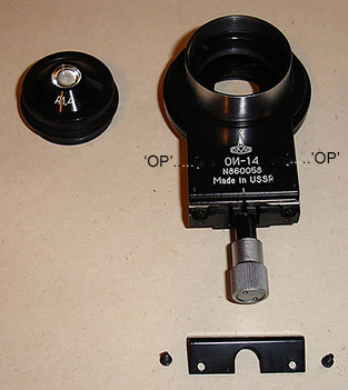
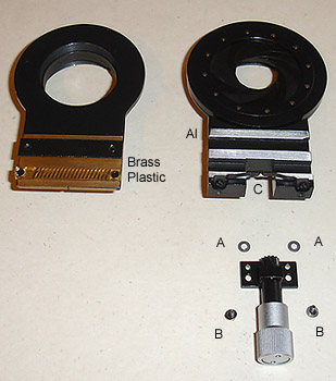
Fig 4 and Fig 5.
First stages of disassembly.
Fig 4. I have removed the optical component of the condenser by holding the polished metal ring and turning the lens housing anti-clockwise, put it in a safe place for later. The 'L' shaped plate with oblique offset markings can now be taken off by removing two screws seen either side of the knurled aluminium oblique control.
Fig 5. remove the knurled aluminium oblique control by turning the condenser upside down and removing two small screws labeled 'B', now you can pull away the control. If you like at this point you can check how stiff the rotation is, if rotating smoothly by itself there is no point doing any more to it but if solid [quite possible] drop it into the small pot of white spirit to soak whilst you work on the rest of the unit. As you remove the oblique control you may find tiny thin washers used as shims marked 'A' in Fig 5. to increase the distance of the gear against the plastic drive, these may or may not be present. If yours does not have these shims and the drive seems to be bottoming out against the plastic drive the effect of which is on rotation of the oblique control the slider seems to make a series of small 'jumps' rather than glide try Tip 2. below, if you leave it bottoming out for any length of time the oblique control will wear out the plastic teeth causing slack in the control. You can see the transparent plastic gear train in Fig 5. marked 'Plastic'. The upper and lower parts of the condenser may be pushed apart to release them into their component parts as seen in Fig 5. you may need considerable force to do this if the grease has gone solid. To clean the brass surface effectively on the upper part I recommend removing the plastic drive train [see Fig 6. below] and brass slider by removing screws 'OP' in Fig 4. this also allows them to be immersed in white spirit and cleaned with a stiff brush whilst carefully holding onto the end with long pliers. The oblique centring position is guided by the sprung metal assembly 'C' in Fig 5. this can sometimes be the cause of a very stiff mechanism even when all the parts have been cleaned up due to too much tension in the metal so you may wish to remove it from its mount by simply pulling it out from its fixing position and bend flatter by hand.
Note 3.
The plastic drive train is held in position with a countersink and pan head screw, these must be replaced in the correct position on re-assembly otherwise you can crack the plastic possibly beyond repair. If in doubt on their positions use a magnifier to view the drive train. As I have shown the upper plate in Fig 5. the countersunk screw is on the left hand side catching the light of the flash gun but this could easily be the other way round on yours, provided the screws match the holes all's well. There is a good reason to use this method of fixing since the countersink screw centers one end accurately whilst the other may be adjusted very slightly using the pan head screw for optimum feel of the oblique control, ie: not stiffening up as you reach one end, indeed, before fully tightening the pan head screw and brass guide after cleaning you may wish to move the oblique control end to end this will self centre the pan head and guide for optimum position, now tighten up, a small error can make a big difference in the feel of the control.
Tip 2.
Push the base of the oblique control assembly [after cleaning] onto a piece of sellotape, cut round the shape with a sharp modeling knife or small scissors and punch through the holes with the end of the scissors, when you re-assemble the tiny increase in height created by the sellotape should be enough to stop bottoming and prevent damage of the gear against the plastic. If one layer is not enough repeat the process. This is often easier than sourcing tiny washers of the right diameter and thickness.
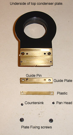
Fig 6.
Underneath of top plate showing component parts ready for re-assembly.
A typical underneath shot of the top plate assembly after cleaning, the brass looks bright, plastic gear train clean and teeth free of grease and all parts are ready for re-assembly. Notice one of the two guide pins just resting at present on the brass guide plate in Fig 6. these often fall out on disassembly and need relocating in the holes as you orientate and tighten the plate, they should remain in position once everything is tightened up although may need pushing [or tapping] fully home before fully tightening. The guide plate is shown the wrong way up to allow viewing of the cleaned edges, on re-assembly this would be offered up to the main top plate the other way up. Notice also over its long 30+ years of life even though the screws are correctly located with their respective holes the countersunk end of the plastic drive train has a small crack most likely caused by overtightening on the assembly line since this is how I found it on refurbishing. It is quite possible that your own condenser brass surfaces looks decidedly poor with dark green blotches from hardened grease and dull blackened areas. If white spirit cannot shift these hardened greases you may have to resort to drying the parts off and scraping the residues off with a very sharp flat blade, once the majority is off you can polish up the surfaces with a high quality brass cleaner [I have used some old 'Brasso' liquid in preference to the dry 'Duraglit' range in the UK] you don't want it too abrasive, finally clean up the surfaces with alcohol to remove traces of the cleaner or rinse under the hot tap whilst scrubbing with an old toothbrush immersed in washing up liquid. Only very small quantities of Nye grease is needed, a tiny amount on all the brass rubbing surfaces is all that is required I then use my little finger to smooth to a thin film, leave the plastic gear train free of new grease, no lubrication is needed on this part on re-assembly.
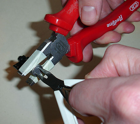
Fig 7.
Removing the fixing plate of the oblique control.
It is possible that the LOMO technicians are out to get you and bundled a pile of 'tank' grease into the oblique control this will show up as a very stiff motion. When it is working correctly by itself it should be very free running maybe with just with a little damping grease if desired. To disassemble the unit grab hold of the knurled aluminium control with a pair of substantial electricians pliers as shown in Fig 7. and turn the inner fixing plate anticlockwise with the pin nosed pliers often used for electronics applications.
Note 4.
You may be lucky enough and still have your LOMO tool for doing this job looking like a large flat key with two small prongs sticking out but they tend to be quite rare especially if your microscope was bought secondhand, these being easily lost through the years by successive owners.
Tip 3.
We don't want to damage the nice anodised aluminium finish on the oblique control so if using pliers wrap some protective tape around the jaws to prevent damaging the finish as shown in Fig 7. The pliers I use also have a gentle curve cut out of the centre of the jaws rather than a completely flat jaw this makes the grip much easier, you can just about see this impression through the tape above.
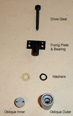
Fig 8.
Oblique control disassembled.
The above picture shows the oblique control disassembled into its component parts, the grease has probably got into the bearing where the drive gear runs so putting all the parts into white spirit, using a stiff brush to remove debris and cleaning off hopefully will improve matters, allow the parts to dry and if necessary immerse them all in alcohol to remove traces of spirit. The only place to add a little oil or grease is the drive shaft running through the bearing to prevent locking up after time. Again as with most LOMO gear the washers may or may not be present, these fit into the cut-out at the back of the knurled outer casing, the springy metal washer creating a little friction to remove slack in the drive. On re-assembly you must get the tension just right, too tight and the drive seizes up, too loose and the drive moves about in its bearing. This adjustment is controlled with the knurled outer casing and then fixed in position with the inner plate acting against it, several attempts maybe needed to get the 'feel' to your liking. First screw on the knurled aluminium outer on the drive shaft until the gear is just starting to tighten up, then back off about an 1/8th turn then screw on the inner fixing plate shown in Fig 8. using the pliers method discussed already except we are now tightening the plate clockwise.
Well by now we should have most of the condenser nicely cleaned up ready to start on the most difficult part of the refurbishing project... the diaphragm.
Working on the top plate and diaphragm.
I have never understood grease being used on diaphragms yet LOMO [and Zeiss on their earlier stands] did use grease on the blades and in the diaphragm mechanism itself, why? I don't know, I can think of no reason whatsoever why they should do this. When I refurbish the condenser and lamp diaphragms [several in the past] I always reassemble completely dry, the parts meticulously cleaned firstly with white spirit and brush to remove grease deposits then each blade is soaked in alcohol and dried off. The ease and running of the refurbished mechanism is a joy to use compared to stirring the 'porridge' of a greased up version and is much easier to set without disturbing the condenser sub-assembly especially noticeable at high magnifications. Some patience is necessary when working on these units, the hardest one I have worked on was a seized diaphragm in a Zeiss Apl-Acr phase condenser, the diaphragm unit and blades are much smaller than normal to fit in the turret in comparison with a typical substage Abbe condenser. I am sure there are many variations on a theme and different owners will have their own methods of re-assembling a condenser diaphragm but I shall discuss mine.
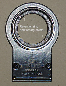
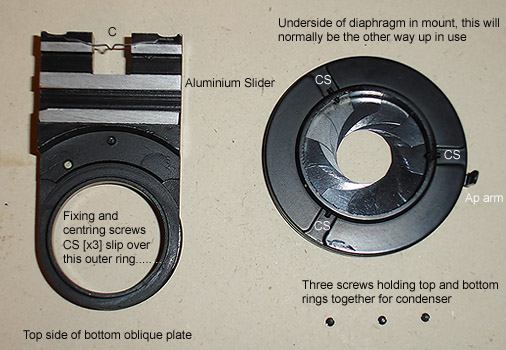
Fig 9 and Fig 10.
Main parts of the diaphragm.
The upper side of the top plate assembly can be seen in Fig 9. where you can remove the retention ring by turning points 'T' whilst holding the plate rigidly. You should only have to do this if the rotation of the oblique condenser is seized or very stiff. An alternative to removal is to immerse the whole plate in white spirit and leave for a while, remove and start twisting, if it comes free dry off, there should be enough grease left in the mechanism to allow free rotation but the danger of seizing up at a later time is possible. To remove the retaining ring you may have to make your own tool a similar one of which I discussed in the rotating stage article.
In Fig 10. the sprung centring for the oblique adjustment can be clearly seen as marked 'C' at the top of the left image and instead of a brass slider we now have aluminium as shown. To start work on the diaphragm we must loosen the three centring and fixing screws marked 'CS', these screws are specially pointed and are very tiny, if lost you may have a hard time getting back to a good working unit. The screws should never be removed completely only loosened sufficiently for the diaphragm housing to be withdrawn from the mount. Start with one screw, loosen by one turn, then the next and last, the diaphragm mechanism should now be loose but may need further turns of the three screws to remove. These screws provide centring of the diaphragm with respect to the optical light path so provided the alignment was correct in the first instance whatever you do to one screw do to the other two. Usually about two turns on each retaining screw 'CS' will allow the diaphragm unit shown in Fig 10. to be withdrawn from its mounting plate.
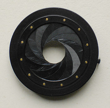
Fig 11.
High quality LOMO diaphragm housing seen from the top.
Note the brass pins holding the blades in place around the perimeter, these near 'circular' multiblade diaphragms when in good condition are much better quality than either Zeiss or Leica offer on their modern microscopes typically having only six blades looking like a hexagon! This type of quality can also be found in many of the older quality stands including the Zeiss 'Standard' range and the Wild M20.
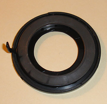
Fig 12.
Partly dismantled. The aperture ring casting.
With the diaphragm housing placed on the table with the aperture arm facing upwards remove three tiny screws around the perimeter of the diaphragm housing the screws of which are shown at the bottom of Fig 10. allowing the two halves of the housing to be prized gently apart with a tough but sharp blade like a penknife. Work around the edge slowly rather than prizing one point only and make sure the housing is placed on a good surface while you do this or the whole assembly might fly apart in a shower of bits! You will then be confronted with Fig 12. above and if you look at the reverse side of the aperture ring after removal as described below you will see radial slots cut out of the casting these engage with the free ends of the blades shown in Fig 16. creating the variable aperture opening as you swing the aperture arm from maximum to minimum.
Carefully pull off the aperture ring [one casting] and you should see something similar to the completed unit shown in Fig 16. it is quite possible depending on the grease and damage that you may see a jumble of blades and thick grease and until you thoroughly clean all the blades, housing and ring in spirit and the blades again in alcohol you will not be able to see what can be done especially if some blades are damaged. With only one or two blades damaged you may be able to get some sort of diaphragm working because all the blades work independent of each other but the aperture will not be perfectly round, however, it could be better than nothing if you have no alternative.
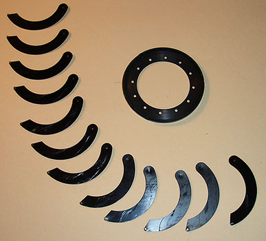
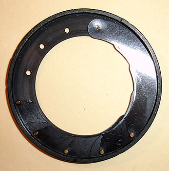
Fig 13 and Fig 14.
Fig 13. Twelve 'blue metal' blades make up the diaphragm.
Fig 14. Select a hole and start building up the diaphragm.
Start building the first layer of blades in an anticlockwise direction on the underside of the top housing ring marked with the aperture numbers 30-6 appearing printed upside down. Offer the curved end with brass pin pointing down into the holes and the angled ends free, laying each successive blade over the last with the pin engaging its respective hole, any grease left on the blades could make the job harder when you reach the final stages so get them 'squeaky clean' before you start.
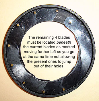
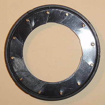
Fig 15 and Fig 16.
Fig 15. The last of the easy blade placing taking less than two minutes to reach this point.
Fig 16. All twelve pins are located and nearly ready to replace aperture ring, see below.
Fig 15. the first layer of blades is complete, now it gets more difficult feeding the four remaining blades beneath the ones already in position. I hold these blades down gently whilst coaxing the new blades underneath the one marked << at the top. You are working blind and patience is required to locate the last two blades into their respective holes but with a bit of luck you should be able to complete the ring in less than 15 minutes as shown in Fig 16. Now comes a tricky part of delicately moving all the upper pins in about 2mm with the tip of a screwdriver ready for them to engage the outermost edge of the slots in the aperture ring otherwise the aperture cannot be set on rotation.
Offer the aperture ring to the blades, make sure the aperture arm is facing upwards and place it above the widest setting of '30' so when you close the aperture the diaphragm will be calibrated correctly. The pins should be roughly in the correct position now and after coaxing each of them into their respective slots with a screwdriver the two halves should come fully together. A little twisting against each other and the tiny screw holes should match between the upper and lower halves, this will be confirmed by looking at the aperture slot where the ends of the upper and lower cut-outs will match. Check the operation of the diaphragm and replace and tighten the three screws around the perimeter.
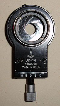
Fig 17.
Looking down at the completed condenser with optics still to be placed.
When you have completed the condenser diaphragm assembly and re-fitted the three tiny screws holding the two halves together you can refit the diaphragm to the rest of the condenser tightening with the three centring screws marked 'CS' in Fig 10. Make sure the diaphragm ring is pushed fully home on its mounting ring marked in the left image of Fig 10. and position the unit so all three screw heads are accessible, this also conveniently centres the swing of the aperture arm in the condenser directly opposite the oblique control. If you have the centring screws in the correct positions then looking down into the condenser as in Fig 17. the aperture should look central in the mount if not try repositioning all three centring screws until the diaphragm is central.
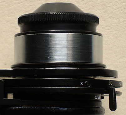
Fig 18.
Side view of completed condenser.
Fig 18. shows part of a fully refurbished condenser with one of the three screws 'S' that secures the two halves of the diaphragm housing together and the aperture arm set at its widest aperture of 30 [mm]. Just below and left of the arm one of the three centring screws 'CS' can be seen which has the dual role of both centring the aperture with respect to the optics and holding the diaphragm assembly onto the main body of the unit, these tiny screws have specially sharpened points and would be difficult to replace if lost, they should not be removed but loosened a couple of turns each to let the diaphragm housing come away from the main body . See also Fig 10.
Final checks and cleaning.
At this point it is worth checking everything is working smoothly including the rotation of the condenser in the mount which should have a smooth feel with no snagging and the oblique left-right motion again which should be smooth and free of stiffening at the extremes which could suggest misalignment of the brass guide or plastic gear train. The diaphragm should be very easy to adjust only stiffening below the 6 mm aperture point as the blades become fully meshed. An inspection of the optical parts especially the top element is a good idea, if OK I don't do unnecessary cleaning but if a clean is required I follow the procedure below.
I do not use isopropyl alcohol on glass elements especially where Zeiss optics are concerned but favour the use of a blower brush to remove large specks of dust then the blower together with a sable brush to remove small specks and if a large area is soiled with grease maybe as you found it having bought it from auction I use a small amount of distilled water mixed with a couple of drops of washing up liquid in a clean saucer applied to a piece of wipe shown below.
The wipe is not wet but well dampened and the glass is left to dry in a few seconds applying the final clean with a few drops of 'Photographic Solutions Eclipse' on a small piece of wipe. These are good quality cleaning products for camera lenses and there are many similar products on the market both in the UK, Europe and U.S.A but I have found both the wipes and the liquid excellent leaving no smears or residue.
If the lens is only slightly marked I blow any dust off and go straight to the 'Photographic Solutions' cleaning liquid. If you use a sable brush remember to thoroughly blow out the brush after the lens cleaning so you don't contaminate your next lens, I keep a high quality delicate sable brush in a box just for this purpose, occasionally washing it out as well and left to dry naturally.

Fig 19.
'Photographic Solutions Eclipse' and matching wipes.
Conclusion.
These are my methods for going about the work on the condenser, the same principles can be applied to other delicate parts of the microscope, everybody has their own methodology for these jobs but I hope anyone not familiar or been put off doing their own maintenance may now have a few guidelines on attempting such jobs. Don't be satisfied with a stiff oblique control or none rotational condenser, transform it to one that glides and spins freely and you can be sure it will last a whole lot longer due to relieving stresses within. A thorough clean and correct use of lubricants will allow the mechanics of your condenser to work smoothly and efficiently for at least 10 years and may be much longer with no further maintenance... a job worth doing.
Details of lubricants, cleaners and links to my previous related LOMO articles.
Related articles:
Russian LOMO microscopes - notes on refurbishing and the use of special Nye lubricants. Click here.
LOMO Biolam microscopes - notes on refurbishing seized rotating stages. Click here.
Also of possible interest - simple LED illumination for microscopes. Click here.
Details of lubricants and cleaning products:
To view details on Nye lubricants visit their website. Click here.
Nye lubricants and useful tools for the hobbyist and microscopist visit the German website Micro-tools.
'Photographic Solutions' U.S.A. lens cleaning products are available from Warehouse Express in the UK.
Comments to the author, Ian Walker, are welcomed.
Published in the March 2006 edition of Micscape.
Please report any Web problems or offer general comments to the Micscape Editor .
Micscape is the on-line monthly magazine of the Microscopy UK web site at Microscopy-UK
© Onview.net Ltd, Microscopy-UK, and all contributors 1995
onwards. All rights reserved.
Main site is
at www.microscopy-uk.org.uk
with full mirror
at www.microscopy-uk.net