In recent issues of this magazine a number of excellent articles by Hans Loncke of the Netherlands and Alvaro de Azevedo of Brazil have described techniques for grinding homemade biconvex lenses and constructing simple microscopes, including replicas of those made by Anthony van Leeuwenhoek. While the photos taken through the microscopes in these articles clearly show an impressive amount of magnification, the magnifying powers of these homemade lenses remain somewhat unclear. Since I was interested in the idea of producing lenses with specific magnifications, I decided to concentrate first on devising a way to determine the magnifying power of lenses before trying my hand at making my own. What I describe here is a relatively inexpensive method I came up with for measuring the magnification of homemade simple microscope lenses to within an error of less than 2% using a laser pointer and an electron microscope grid. Using this method, and the techniques described by Loncke and de Azevedo, I was able to reproducibly craft biconvex lenses and verify that their magnifications were, on average, within 3% of the desired magnifying power of 118X.
A downloadable version in Adobe Acrobat format is available here (0.9 Mbytes).
Over the years a variety of articles have described ways for amateurs to make their own single lenses and build simple microscopes of surprisingly high magnification (see FURTHER READING). One of the earliest and most influential of these is the classic article by Albert G. Ingalls that appeared over fifty years ago in the Amateur Scientist column of Scientific American. Ingalls shows how to make small glass beads that can be mounted between two plates to make a 'van Leeuwenhoek-type' single lens microscope. With few exceptions, the majority of articles written after the Ingalls article have all utilized small glass beads as lenses. Recently, however, amateur lens crafting has taken a much more sophisticated turn, particularly with the articles of Hans Loncke of the Netherlands and Alvaro de Azevedo of Brazil that show techniques for grinding homemade biconvex lenses. Unfortunately, one shortcoming of nearly all these articles (including that of Ingalls) is that there are rarely any means presented for measuring the magnification of the homemade lenses that are produced. The photos of microscopic images that accompany these articles clearly show that a high degree of magnification has been achieved, but of exactly what power is almost always unclear. I was very interested in trying my hand at replicating the lens grinding techniques of Loncke and de Azevedo to see if I could produce my own lenses possessing specific magnifications. However, to accomplish this, I first had to devise a way to accurately measure the magnification of homemade lenses.
I began by studying a very well known paper by J. van Zuylen that describes how he went about measuring the optical properties of lenses in eight of the remaining original van Leeuwenhoek microscopes. To measure the magnifying power of these lenses, van Zuylen built a customized microscope that projected a collimated image of a test scale through a van Leeuwenhoek lens. Then, using a filar micrometer mounted below the eyepiece of the microscope, van Zuylen measured the dimensions of the magnified test scale image. Since a quick look at my Edmund Optics catalog convinced me that building my own custom microscope of this sort was far beyond my budget, I began considering less costly alternatives. It occurred to me that an inexpensive laser pointer might work as a collimated light source. Also, I remembered reading an article a number of years ago by Alan Shinn in which he described how to use an electron microscope specimen-mounting grid to estimate the magnification of homemade lenses. These grids are inexpensive and very precisely manufactured thin metal screens with a distance between holes measuring in the range of microns. Thus, I suspected that I might be able to use a simple laser pointer to cast a collimated image of an EM grid through a homemade lens and then measure the projected image to determine the magnification of the lens. The diagram below shows the general idea behind this strategy.

Initial experiments conducted using a laser pointer, a glass bead and a pinhole punched in a piece of aluminum foil convinced me that it was worth spending the money to purchase some EM grids and build an imaging apparatus to precisely measure these laser projected images. The EM grids I bought were Veco 75 mesh copper grids with a center reference from Ted Pella, Inc. (cat # 12555-CU) and cost $15.90 for a vial of 100. The laser pointer was a battery operated Class IIA laser with a red emission wavelength of 630-680 nm and an output power of less than 1mW that I bought at the local pharmacy for $3.99. I also bought some precision-made borosilicate glass balls to use as test lenses. These I obtained from the Winsted Precision Ball Co. in three sizes: 3/32"(2.38 mm), 4/32"(3.18 mm) and 5/32"(3.97 mm) in packs of 100 costing $12.53, $9.59 and $10.67 per pack, respectively. Finally, I bought some high-quality ball lenses from Edmund Optics to use as a second set of test lenses. These lenses are typically used in couplings for joining fiber optic cables and are made from a variety of optical materials. I chose the ball lenses made from sapphire (Al2O3) because they were the least expensive and also because they had an index of refraction of n = 1.77, a value that should produce images that are measurably different from that of the borosilicate glass balls (approximately n = 1.51). Three sapphire ball lenses were ordered in the same sizes as the borosilicate glass balls at a cost of $11.00 each. Next, I needed to permanently mount an EM grid in the center of the laser beam emission path and then come up with a way to easily attach and remove lenses for testing. The layout I came up with is shown in the diagram and photos below.
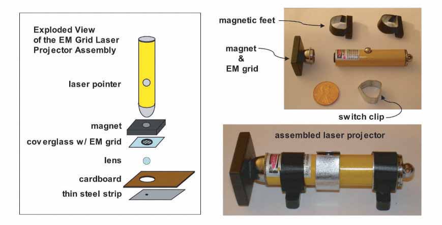
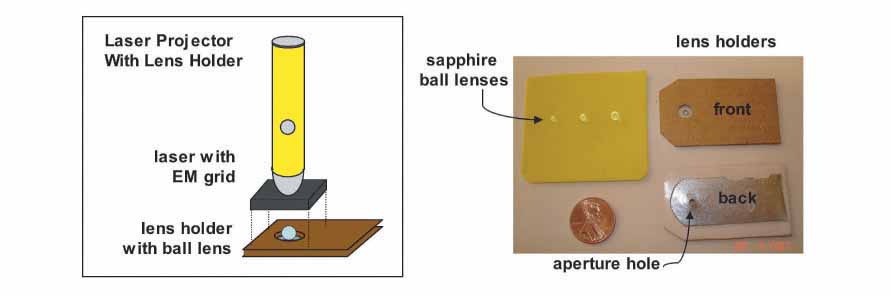
First, I mounted the EM grid onto a glass coverslip using tweezers to handle the grid and cellophane tape to affix it to the glass. I cut two very thin strips of tape (1-2 mm wide) with a razor blade to mount the grid by its edges to the glass, being careful not to bend or damage the grid. Using a diamond pen, I cut the glass to an approximately 1 cm square piece with the grid located at the center. Next, I superglued a magnet with a hole in its center to the head of the laser pointer. After the glue dried, I positioned the coverglass with the grid over the hole in the magnet (grid side facing the beam) and centered the grid in the beam while the laser was on. I was careful to never look directly into the beam while doing this, but instead watched the laser dot reflected off the coverglass. I also fashioned a small clip out of thin metal to attach to the laser pointer for hands-free operation; rotating the clip depresses the switch button and keeps the laser on. I also made two magnetic feet to attach to the laser to make it easy to position during imaging. The purpose of using a magnet on the laser head is to provide a convenient means for attaching the lens holder and keeping it in place. The cardboard lens holder has a thin steel strip glued to it that is attracted by the magnet on the laser head, thus making it easy to quickly mount lenses to be tested and center them in the path of the beam. The hole in the cardboard was made using a standard size paper hole punch and the aperture hole in the steel strip was drilled using a 2 mm drill bit. The steel strip was also slightly indented (with the aperture hole at the center) to make a slight depression in which the lens would sit. The front and back of two lens holders are shown in the photo below along with the sapphire ball lenses described earlier.
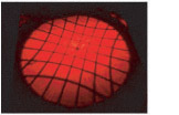
Finally, I constructed an imaging stand to hold the laser projector at a constant height so that measurements could be made of the projected image. A photo of this along with a laser-projected grid image is shown below.
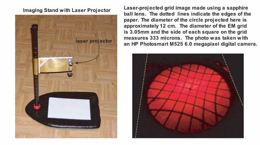
The imaging stand was made from a swimming pool paddling board and the handle of a lacrosse stick. An adjustable arm for holding the laser over the board was made from a sheet of brass with a steel strip added for the magnetic feet of the laser projector to attach to. The lacrosse stick was marked off in inches to indicate the height of the arm over the board. A meter stick was used as a secondary means of exactly measuring the height of the lens over the board after initial positioning of the arm and adjustment of the lens. As can be seen in the photo above, the laser-projected grid images that are produced are very clear, crisp and turn out to be rather easy to measure. A quick survey using the ball lenses that I had purchased indicated that the magnification was obviously increasing with decreasing lens size and was increased in the sapphire lenses relative to the borosilicate glass lenses, as expected. Below are a series of computer-generated drawings made from laser-projected grid images that demonstrate the effects of ball lens size and index of refraction on the projected image.
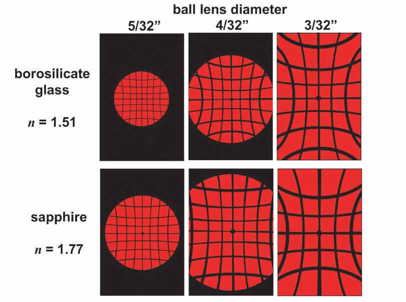
The computer drawings shown above were copied from drawings made by first projecting the grid image onto a piece of paper with the room lights dimmed, then sketching the image with a pencil. The height of the lens over the paper in each drawing was 9 cm. Each rectangle represents the size of the paper used for the drawing, the dimensions of which were 15.2 x 23.0 cm. The clarity and reproducibility of these images convinced me that I should be able to very accurately determine the magnification of unknown lenses. First, however, I needed to study the lens equation and calculate what the magnifications were of the sapphire and borosilicate glass test lenses that I was using.

The general form of the lens equation is shown above. This equation relates all of the variables involved in governing the optical properties of any lens. Since we are interested here in only symmetric biconvex lenses (i.e. lenses in which the radius of curvature is equally convex for both faces) and ball lenses, the general equation can be simplified to produce the two equations shown below.


In these two equations: f = focal length, R = radius of curvature, d = lens thickness, and n = index of refraction. The radius of curvature (R) of a lens is the radius of the sphere with a surface curvature matching that of the face of the lens. The thickness (d) of a lens is the distance between the center of the two faces. Note that for ball lenses the radius of curvature is equal to ½ the thickness or diameter of the lens. The focal length (f) is the distance between the center of the lens and the point where light passing through the lens converges (i.e. the focal point). Finally, the index of refraction (n) is a value representing the extent to which light is refracted (bent) by the material from which the lens is made. Different materials possess different indices of refraction. The significance of each of these variables is further illustrated in the series of diagrams shown below.
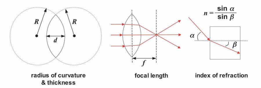
Given the focal length (f), the magnification (M) of a lens can be derived using the formula illustrated below.
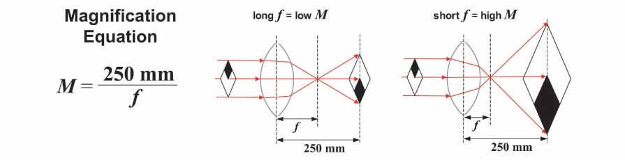
The 250 mm value that appears in the magnification equation arises from the fact that the size of an image increases with increasing distance from a lens. In order to meaningfully compare the magnifying power among lenses, a standard distance has been agreed upon, i.e. 250 mm (approximately 10 inches), which is an estimate of the closest distance at which the eye can focus. Using the ball lens equation shown above, along with the index of refraction for borosilicate glass (n = 1.51) and sapphire (n = 1.77) and the diameter (thickness) of each lens, I was able to calculate the focal length and magnification of each of the test ball lenses examined previously. These values are shown in the table below.

Once I had calculated the magnifying power of each of the borosilicate glass and sapphire test lenses, I moved on to measure the magnification of these lenses based on their laser-projected grid images. In this way, I was able to compare the actual or calculated magnifying powers shown above with measured values and thereby assess the accuracy of the laser-projected grid image measurement technique.
The procedure I used to make measurements of laser-projected grid images ran as follows. After mounting a lens on the projector, I first positioned the arm of the imaging stand to a height of approximately 4 inches (10 cm) above the surface of the board. I then mounted a clean sheet of paper on the board and with the laser turned on, adjusted the lens holder so that a single grid square was evenly centered in the field of the projected image, as shown by the starred square in the left portion of the diagram below.
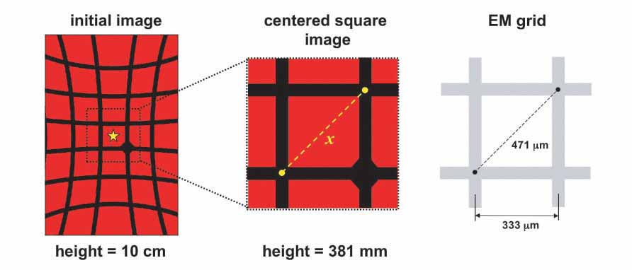
Due to the curvature of the lens, the field of view becomes increasingly distorted as one moves further from the center of the image. Thus, to obtain accurate magnification measurements, it is critical that the measured grid square be positioned over the exact center of the field as closely as possible. After centering a grid square image, the adjustable arm was repositioned to place the lens at a height of exactly 15 inches (381 mm) over the surface of the board. This height was verified to within 1 mm using a meter stick. The grid image produced at this second height is much larger and also fainter since the same quantity of light is now being cast over a larger area. Also, it is easy to lose track of which square was centered after moving the adjustable arm. Therefore, I always made sure that the centered square had the EM grid center reference marker in one of the corners so that I could easily return to the same square again after moving the arm. Next, I dimmed the room lights and used a pencil to make two dots on the paper marking the location at the corners of the diagonal of the grid square image as shown in the center diagram above. Again, it is important to make these dots in the exact center of the intersection of the two grid wires or else the magnification measurement will be inaccurate. Finally, I turned on the lights and measured the distance (x) between these two dots with a ruler to the closest 0.5 mm. Six independent measurements for each lens were made in this manner.
Unlike the previous calculation where the focal length (f) was utilized to arrive at a value for magnification (M), this time I needed to take a different approach since the focal length will be unknown in the homemade lenses to be tested later. When the focal length is unknown, the magnification can be derived as simply the ratio between the apparent (magnified) size of an object and its actual size. For the laser projected grid images described here, this translates to the size of the projected image at 250 mm (D) divided by the size of the grid. To calculate the magnification from the grid images, the mean value (average) of 6 grid image distances (X) was computed and first divided by the height of the lens over the board (381 mm) to yield the grid image size per millimeter of distance from the lens and then multiplied by the standard distance of 250 mm to yield the size of the image at the standard distance (D). Next, the image size at the standard distance (D) was divided by the size of the original object (0.471 mm = the comparable diagonal distance on the EM grid shown in the diagram on the right above) to yield the measured magnification value (Mm). The two formulas given below show the steps in this calculation.

The table below shows the initial mean distance values (X), the calculated size of the image at the standard distance (D), and the results of the magnification calculations for each lens. The measured magnification values (Mm) were compared to the actual values (M) determined earlier and the percent error (%E) between the two is also shown.
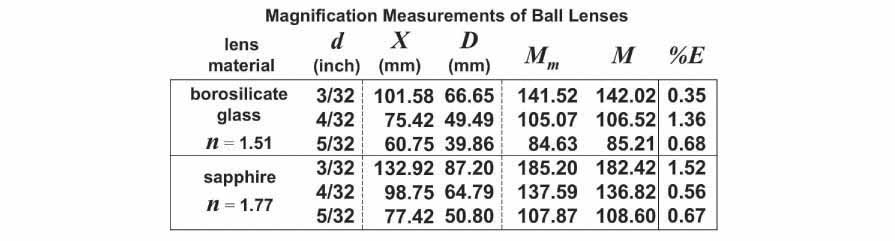
As can be seen from the table above, the percent error in the measured magnification when compared to the actual magnification ranged between %E = 0.35 - 1.52%, with an average value of 0.86%. Thus, the laser-projected grid-imaging technique was found to be a relatively simple means for measuring the magnification of lenses to within an error of less than 2%. With this technique in hand, I next turned to the question of crafting my own biconvex lenses using the methods described in the articles by Hans Loncke and Alvaro de Azevedo.
As mentioned in the article by Hans Loncke, the Boerhaave Museum in the Netherlands is home to three of the microscopes originally crafted by Anthony van Leeuwenhoek (1632 - 1723). One of these is a small brass microscope (shown on the left below) having a magnification of 118X, as measured by J. van Zuylen.
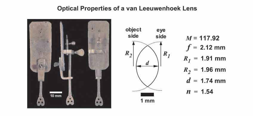
Since the optical properties of the lens in this microscope have been thoroughly documented, I decided to see if I could use the lens grinding techniques described by Loncke and de Azevedo to make a 'replica' van Leeuwenhoek 118X biconvex lens.
First, I carefully studied the list of optical properties reported by van Zuylen for this particular van Leeuwenhoek lens. A scale diagram of the lens is shown above along with the list of its optical characteristics. Since the borosilicate glass balls that I planned to use as lens blanks have an index of refraction slightly lower than that of the glass used by van Leeuwenhoek, I knew that to arrive at a 118X lens I would have to compensate for this by slightly altering the lens thickness and radius of curvature. Thus, using the biconvex lens equation described earlier, I made a graph plotting the relationship between magnification (M) and radius of curvature (R) for borosilicate glass lenses (n = 1.51) with a variety of thicknesses (d = 1.75 mm, d = 2.00 mm and d = 2.25 mm). This graph is shown below on the left along with a scale diagram depicting the corresponding 118X lenses shown on the right.
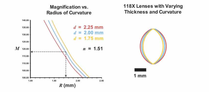
Inspection of the graph above suggested that a lens thickness of d = 2.00 mm and a radius of curvature of R = 1.75 mm should result in a lens with a magnification very close to 118X. In the articles by Loncke and de Azevedo, steel ball bearings were pressed into pieces of softer metal to form concave impressions that were then used as lens grinding bits. I chose 4.0 mm diameter steel ball bearings for this purpose since the 2.0 mm radius of these ball bearings might be expected to yield a concave grinding surface with a radius of curvature very close to 1.75 mm after the addition of grinding abrasive.
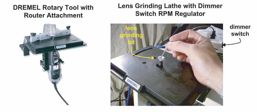
Having a design for a 118X lens in hand, I next went about assembling a lens grinding lathe, similar to those used by Loncke and de Azevedo. I found that the DREMEL Single-speed Rotary Power Tool (Model # 275-02) and Router Attachment (Model # 231) are easily configured to make a very convenient grinding lathe. These items were purchased online from Hechinger Hardware for $36.64 and $26.09, respectively. Since the DREMEL rotary tool that I purchased was the least expensive single-speed model (factory set speed = 35,000 RPM), I needed to find a means of regulating the speed to a much lower number of RPMs. This was accomplished by simply building an outlet box with a dimmer switch to control the power supply to the DREMEL tool. This setup is shown in the photos below.
Next, I fashioned a series of lens grinding bits by pressing 4.0 mm steel ball bearings into a 0.032" (0.81 mm) thick sheet of aluminum using a bench vise. The concave impressions left by the ball bearings were then cut from the aluminum sheet using tin snips and glued to small pieces of 4/32" (3.175 mm) diameter aluminum tubing using superglue followed by reinforcement with a hot glue gun. The assembled lens grinding bits were then allowed to harden for 24 hrs prior to use. The 4/32" borosilicate glass balls, described earlier, were used as blanks from which the 118X biconvex lenses were ground. Superglue was used to affix the balls to the end of grinding spindles made from short lengths of 3/32" (2.38 mm) diameter aluminum tubing. These were also allowed to harden for 24 hrs prior to grinding.
The grinding procedure was similar to that described by Loncke and de Azevedo and went as follows. First, I installed a DREMEL grinding wheel on the lathe and used this to initially flatten the blanks to the appropriate height as shown in the diagram below.
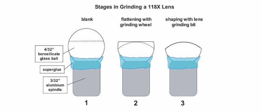
At this step, I found it important to keep the speed of the rotary tool very low or else the glass balls would either come loose from the grinding spindle or develop chips and fractures on the ground surface of the glass. With the aid of a magnifying glass, I could approximate by eye how far the glass sphere needed to be ground. After flattening the blank to the proper height, it was then ground to the desired radius of curvature using a series of three lens grinding bits and progressively finer abrasives. In the first bit I used a diamond paste abrasive (8 - 12 micron particle size) mixed with 80 grit abrasive that I rubbed off a piece of sandpaper. A relatively low grinding speed was used until the lens had acquired a smooth, frosted, match-head like appearance. After the lens had assumed the proper curvature, the grinding paste was cleaned away and a second bit with diamond paste alone was employed at a slightly higher grinding speed. This was continued until the lens became clear and the frosted appearance from the previous step was gone. Again, the lens was cleaned and the last bit was employed using a very fine diamond paste (1 - 2 micron particle size) until the lens became very bright and resilient. As a final step, a small piece of lens paper was placed into the bit and used to polish the lens at a very high speed. The lens was then removed from the spindle using acetone (nail polish remover) and allowed to soak overnight before reaffixing to the spindle and grinding the other face of the lens in the same manner. The diamond paste abrasive used in this procedure was acquired from Diamond Innovations, Inc. and cost $17.73 and $7.34 for 5 grams each of the coarse and finer grained pastes, respectively.
Nine lenses were crafted in this manner and the thickness of each lens was measured using a micrometer as shown in the photos below.
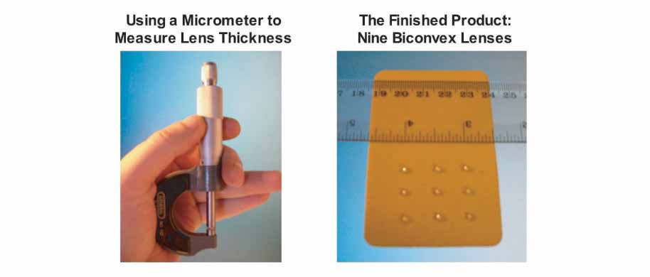
Finally, the lenses were cleaned once more with lens paper and magnification measurements were made for each lens, as described earlier. The results of these magnification measurements (Mm) along with the lens thickness measurements (dm) are highlighted in yellow in the table below.
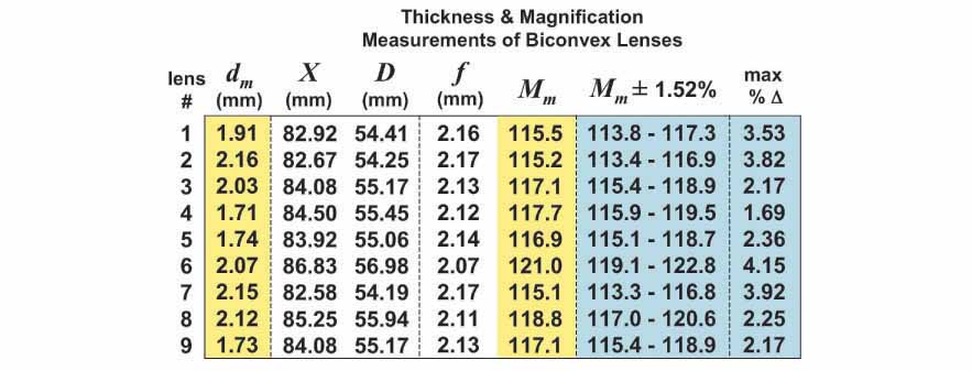
The table above shows that the thicknesses of the lenses ranged between dm = 1.71 - 2.16 mm with an average of 1.96 mm, a value very close to the originally desired thickness of d = 2.00 mm. The magnifications ranged from Mm = 115.1 - 121.0X with an average value of 117.2X, again very close to the target magnification of M = 117.9X. Using the maximum percent error found earlier (%E = 1.52%) as the uncertainty in the magnification measurements (Mm ± 1.52%), the maximum percent difference from the target magnification (max %Δ) was calculated for each lens (both of these sets of values are highlighted in blue in the table above). The max %Δ values represent the maximum amount by which the actual magnification can vary with respect to the target magnification given the uncertainty in the magnification measurements. As can be seen in the table, the maximum percent difference ranged from max %Δ = 1.69 - 4.15% with an average value of 2.90%. Thus, on average, the magnification of the lenses deviated from the target magnification of M = 117.9X by less than 3%.
Overall, the laser-projected grid imaging technique presented here was found to be a very convenient means for assessing the magnification of homemade lenses. However, there are two areas where the technique might be improved upon to yield even more accurate measurements of magnification. Error propagation analysis of the system suggests that the uncertainty in the grid image measurements and those of the height of the lens over the imaging board are the primary sources of error (the variability associated with the dimensional tolerances of the ball lenses and EM grid were found to be negligible). Since the limit to accurately reading a millimeter ruler by eye is fixed, one could improve the accuracy of the measurements by simply increasing the size of the grid images that are projected. A 1 meter square projected grid image would be expected to yield a much more accurate determination of magnification than the 6 - 13 cm projected images measured here. This, of course, would require a larger imaging apparatus and a more powerful laser than the battery operated laser pointer that I used for projecting images. Another interesting prospect for future work might be to measure the degree of image distortion as one moves from the center of a projected grid image. This distortion appears to correlate with the radius of curvature of the lens, thus, measurements of this distortion might provide an easy means for determining R. Finally, it occurred to me during the preparation of this article that it might be possible to use prepared slides, instead of an EM grid, to laser-project microscopic images of thinly sectioned specimens. In conclusion, the laser-projected grid imaging technique demonstrated here has proven to be a relatively inexpensive and easy means for accurately determining the magnifying power of homemade simple microscope lenses.
The author welcomes comments.
Ingalls, Albert G. (1953) The Amateur Scientist: On the Fascination of Microscopy and Some Curious Amateur Observations of the Moon Scientific American, January 1953 issue: pp. 80-87.
Baker, Roger C. (1991) The Homemade Microscope Science PROBE!, April 1991 issue: pp. 53-62.
Shinn, Alan (1996) To Make a Leeuwenhoek Microscope Replica Microscopy Today, volume 4 #6, January 1996 issue: pp. 14.
Shinn, Alan (1996) To Make a Leeuwenhoek Microscope Replica Web version with additional links on estimating the magnification of a homemade lens.
Carboni, Giorgio (1996) A Glass-sphere Microscope www.funsci.com
de Azevedo, Alvaro A. (2005) Exploring the Possibilities of Single Lens Microscopes Micscape, September 2005 issue.
de Azevedo, Alvaro A. (2006) The Challenge of Grinding Lenses for Single Lens Microscopes Micscape, January 2006 issue.
de Azevedo, Alvaro A. (2006) The Challenge of Grinding a Miniature Biconvex Lens The Citizen Scientist, 13 January 2006 issue.
de Azevedo, Alvaro A. (2006) How to Prepare Abrasive Powders The Citizen Scientist, 10 February 2006 issue.
de Azevedo, Alvaro A. (2006) Improving the Performance of the Single Lens Microscope Micscape, July 2006 issue.
de Azevedo, Alvaro A. (2006) Building A High Power Pocket Simple Microscope Micscape, December 2006 issue.
de Azevedo, Alvaro A. (2007) A Novel Method for Making Miniature Lenses Micscape, June 2007 issue.
Loncke, Hans (2007) Making a van Leeuwenhoek Microscope Lens Micscape, April 2007 issue.
Loncke, Hans (2007) Making an Antoni van Leeuwenhoek Microscope Replica Micscape, July 2007 issue.
The article by J. van Zuylen mentioned in the text is
van Zuylen, J. (1981) The Microscopes of Antoni van Leeuwenhoek Journal of Microscopy, Vol. 121, Pt 3, March 1981, pp. 309-328.
Please report any Web problems or offer general comments to the Micscape Editor.
Micscape is the on-line monthly magazine of the Microscopy UK web site at Microscopy-UK.