USE of the LOGITECH QUICKCAM PRO 9000
for photomicrography
History of a
near-failure, or a semi-success
PART II
see here for Part I
WALTER
DIONI
CANCÚN, MÉXICO
INTRODUCTION
In the first part I
gave the reasons why I decided that it was worth testing the Logitech
camera for photomicrography, since it showed a good performance
on tests as a normal camera. I also indicated why I would use the camera with
the technique called "afocal". To
convince me of its usefulness and quality, I applied a series of
fairly simple tests, since I don't have the slides specially designed to
measure the optical behavior of a camera, which the optical professionals use.
Here I review a) the basic tests, b) the method that
now seems to me is the best to handle this camera, and c) I summarize the
results I obtain in brightfield and the subjects that I consider useful for photomicrography
with this installation.
I tried to keep the
imagery within customary limits, with most of them in 800 x 600 px format. When there are reductions
of bigger photos this is indicated in the caption. Those subjects which should
be shown at scale (1:1) are cropped to size 800 x 600 to be presented here
without resorting to linked images.
A TEST with the MICROMETER
(4 x, 10 x, 40 x, 100 x) comparison of LOGITECH, with MOTIC , and CANON A300
My first test of the photomicrographic quality was to
compare pictures of my Leitz stage micrometer.
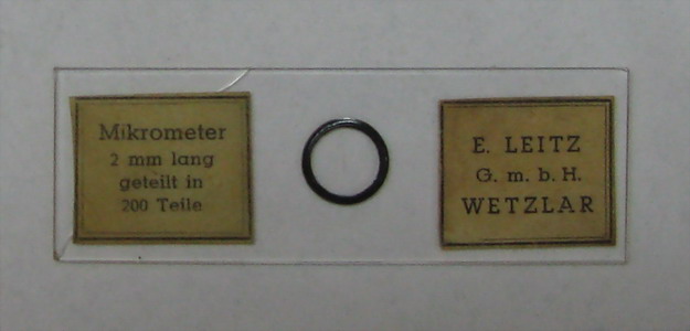
Fig. 1- micrometer
picture
Since I can't display the full 2 mpx images here, nor do I want to overload
the article with excessive linked images, I will include first a reduction of a
complete photo showing the 2 Mpx sensor as a black rectangle with the 0.8 Mpx Photographic
Field (PhF) at its Center (fig. 2; see the
first part of this article) and then use crops of 800x600 px PhF at scale 1:1 (maximum rectangular cropping in the circle of the PhF). I have not attempted
to reduce these images anymore because they are what really defines the electronic
resolution that the camera produces.
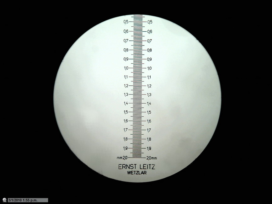
Fig. 2. Micrometer
scale photographed with the 10x, 0.25NA objective with the Logitech 9000. Full
area of the sensor (black rectangle) is 2 Mpx. Utilised area (central disc)
is 0.8 Mpx.
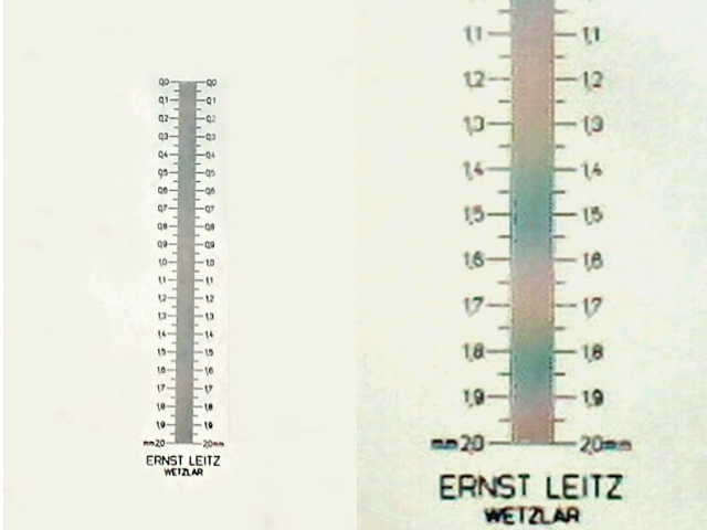
Fig. 3. The
Scale
photographed with obj 4x, and the Logitech. Cleaned background. 320
x 480 crop.
Fig 4 - Expanded crop
of fig 3.to show clearly the lack of digital resolution of the 10 microns lines
of the micrometer scale
Both David Walker and I got consistent results. It is even possible to resolve the 10-micron lines of the micrometer
stage at 640x480.
The behavior of the DC-3 is totally understandable given
its very low resolution (0.08 Mpx). David and I believe that the lack of resolution on the Logitech (repeatedly tested and always consistent) is because with the 4x objective and 10x eyepiece, the micrometer is not covering sufficient pixels on the colour sensor to resolve the 0.01 mm lines, illustrating the importance of matching the image to the sensor size. A 16x eyepiece improves the image - sensor match and resolves the lines. This is illustrated in the additional Figures 4a, 4b below.
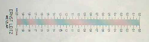
Figure 4a
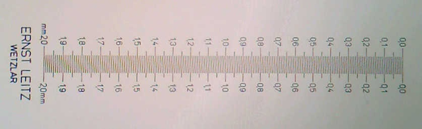
Figure 4b
Figure 4a and 4b: Leitz 2 mm micrometer scale with 0.01 mm divisions, rephotographed with the Logitech at its 2 Mpixel native resolution using the 4x objective.
Fig. 4a uses a 10x eyepiece as in fig, 3 and shows the full 1:1 crop from master image
Fig. 4b uses a 16x eyepiece, and again the full 1:1 crop from master image. The lines are now just resolved but notice the false structure in between the lines created by a moiré type effect. This can occur when the subject detail is near to the sensor resolution and could result in false structures being shown of a real subject. A higher objective mag may be needed to clarify what is real detail when photographing an unfamiliar subject. See the micrometer retaken with the 10x objective in Fig. 5 below where there is no such effect and the images shows a clean resolution.
This study suggests that with the 4x objective on my system, at least a 15x eyepiece is required for imaging with the Logitech.
Several microscopists use this camera in which I call "astronomical
configuration", basically to record videos. If someone wanted to do this simple test with still images I am very
interested in the results.
Several microscopists use this camera in which I call "astronomical
configuration", basically to record videos. If someone wanted to do this simple test with still images I am very
interested in the results.
It is clear
that the Logitech, working at this 0.8 Mpx level is unable to resolve the
micrometer lines with the 4x objective.
Although disappointing, this is understandable, since calculations show
that at least 1.3 Mpx (60% more pixels) are needed to resolve images with the 4x
objective.
So it must
be understood that all images taken with the 4x objective, in this afocal installation will have a
resolution much lower than the observed optical resolution when the preparation
is seen by eye through the microscope.
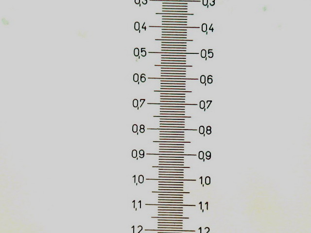
Fig. 5 A cropping at 1:1 of the Logitech image taken with the 10 x
objective. It shows clearly a good resolution of the lines on the scale (compare with
fig. 2)
I save space by not including images with the 40x and 100x objectives,
which show a much better resolution of the scale, of course.
As a comparison
I include an image of the same scale, captured by the objective 4 x, the 10x eyepiece
and the 3.2Mpx Canon Powershot A300 camera. Hand held camera.
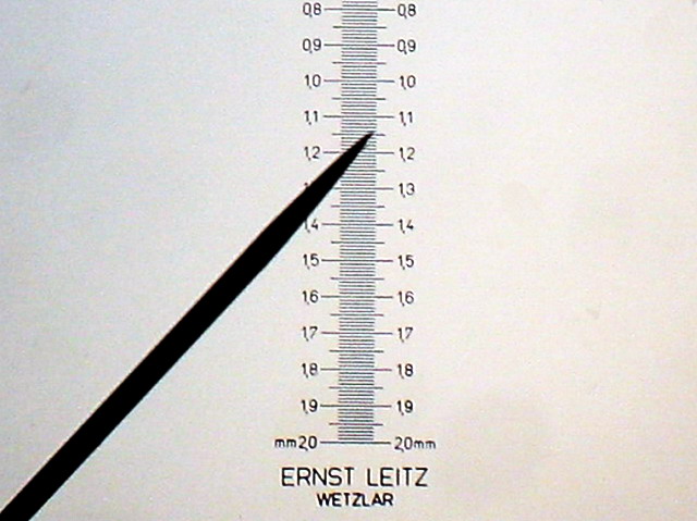
Fig. 6 - Canon A 300 - Cropping 640 x 480, at scale 1:1,
from image of 3.2 Mpx. objective 4x
The Canon with its 3.2 Mpx actually resolves seamlessly the scale projected
by the 4x objective.
TEST
with FIXED PREPARATIONS
Comparing DC-3 vs Logitech
A first test was made on a histological preparation
with a duodenum section stained with HE and mounted in Permount.
DC-3. Objective
40x
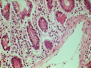
Fig. 7 320x240 px

Fig. 8 - 640 x 480,
LOGITECH
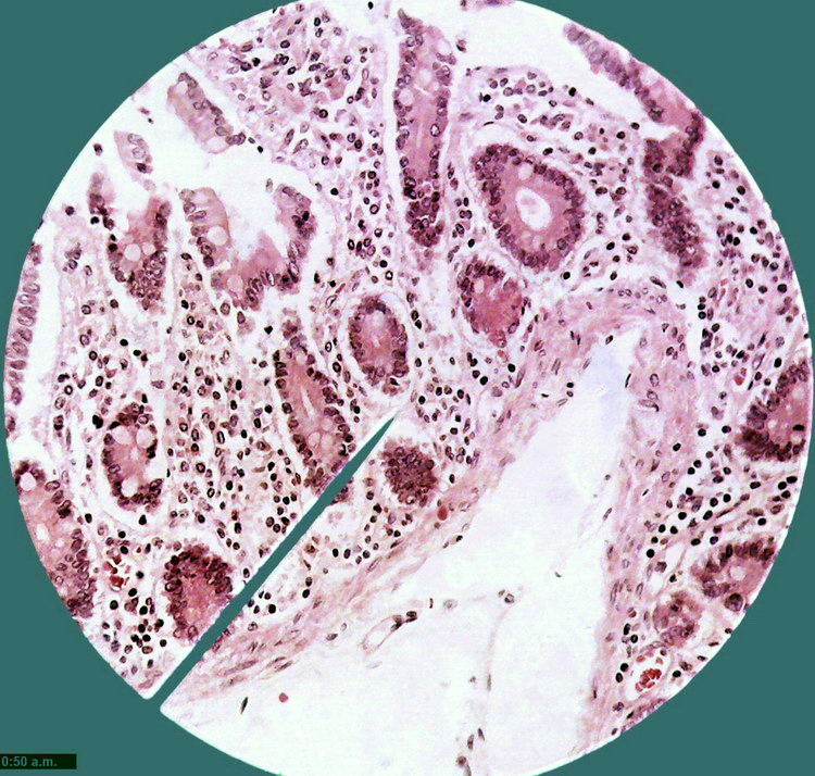
Fig. 9 Total field of view (0.8 Mpx) cropped from
the 2 Mpx image
The logical move would be
to use a circular image to display images captured with the microscope. But a custom
introduced from the use of the first commercial photographic apparatus is to
produce rectangular photos.
Only recently (when new
display methods other than cathode ray tubes were invented) have screens appeared for both
computer and TV that establishes a new standard, which allows us
to view images in a more
elongated form (1:1.6 or even more). See picture 11.
Digital camera makers continue these trends. By now
most cameras have a 1:1.33 format
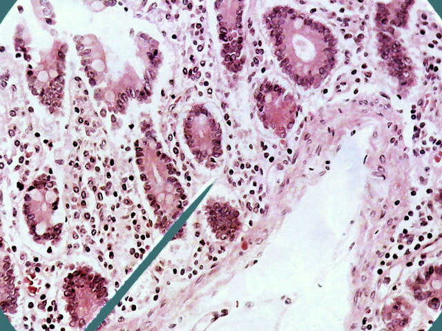
Fig. 10 - 1:1 cropping of the previous
image, at 640 x 480 px similar to the size of the DC-3. The Logitech would
allow an 800x600 px format, with a more wide FV of course.
NOTES
ABOUT EMPTY MAGNIFICATION
It is customary to consider microscope magnification "normal" when using a x10 eyepiece. A
microscope with the generally used objectives (4x, 10x, 40x and 100xOI) could deliver
therefore 40, 100, 400 and 1000 powers. Microscopists
can "increase" power using 15x or 20x eyepieces. However,
all microscopy treatises emphasize that the additional achieved increase is
"empty magnification". The
image resolution provided by the microscope optics is fixed, as is stressed
and it is true, by the Numerical Aperture of the objective. The
eyepiece increase does not add any additional NEW structural detail. Just what was formerly
seen with the 10x, is now seen larger.
Clearly, a fortiori the same constraints apply for the
digital magnification. With
the aggravating factor that careless image increases increase the risk of
pixellation, worsening the view of the subject details.
The theme was tested by taking images of the same
subject (in this case an arteriole filled with blood) and photographing it with
a variety of image sizes, either at the native size (for the camera in
normal configuration) or in upsized
versions using
external resizing software. It will be
used again the image of the arteriole, as it is convenient.
Optics used in all cases was the 40x (0.65 NA)
objective, with the 10x eyepiece.
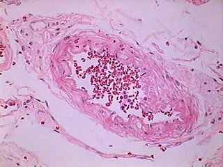
Fig. 12 - DC-3 320x240 Original
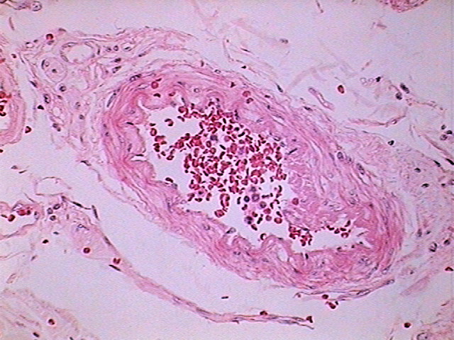
Fig. 13 - DC-3 640 x 480 delivered image
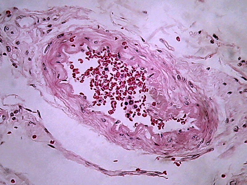
Fig. 14 - Logitech - 800x 600, 1:1
clipping, of the 0.8 Mpx original
From my point of view, in a large percentage of images the information captured by the 40x/10x optical combination, particularly the ease of visual extraction of that information, clearly increases from the DC3 0.08 Mpxs up to the Logitech 0.8 Mpxs.
The
next two images offer a special vision of the subject. The
first (fig 15) is a reduction of the original 2 Mpx, showing the field of 0.8 Mpx with
the image provided by the 100xOI objective of a significant section of the
arteriole,of fig 14 from which a central crop (fig
16) was taken .
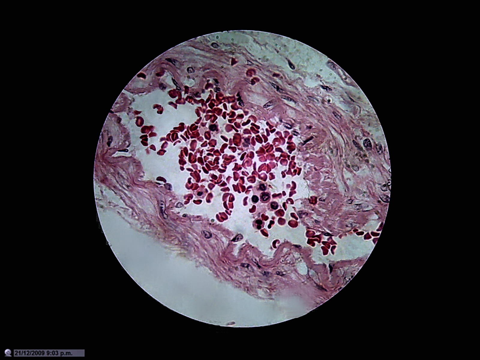
Fig.
15 - Logitech - Objective 100XOI (N.A
1.25) with the eyepiece 10X, reduced from the original of
1600x1200
- click the image to see the full sized image
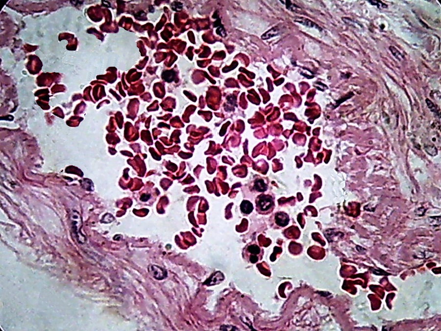
Fig. 16 - 100xOI, no zoom, no post-processing, clip from the 2 Mpx image (0.8 Mpx PhF)
There
is a qualitative leap in using 100xOI with numerical aperture 1.25
objective, with double
immersion , in combination with the 10x eyepiece. The
cropping of 800 x 600 gives of course better information providing a more clear
image, with good size.
My conclusion, I think my readers will share (if
anyone is still supporting these articles) was that the Logitech is
a very valuable tool even if it must be used (as it is here) only as a camera of 0.8 Mpx of digital
resolution.
The
following are the working techniques I adopted, and some comments on their use
and limitations. Some
of the latter do not seem to be easily corrected, and several are shared by
other so-called Microcular cameras, according to the responses I've received to
consultations I've had with some users.
Of
course this is the normal method of work for those who do not have microscopes
equipped with Zernikes phase contrast, or N-DIC (Nomarski Differential
Interference Contrast).
MICROSCOPE
1) The
first
rule is to have the microscope optics extremely clean. In the light pathare the frontal lens of the lamp, didymium filter, condenser, sub-stage filters if
used, the preparation slide itself, the objective of the microscope, the prisms
of the binocular head, the eyepiece, and the camera lens. Any particle on these
surfaces casts shadows in the images background. The
Logitech has a depth of field slightly larger than normal cameras, it reviews,
detects, and displays cruelly, any dirt on the front lens of the eyepiece for
example. Any insistence on this issue (valid for all photomicrography, with any
camera) is justified. A
digital method of disposal (where possible) of these shadows of the background
has been added in a Topical Tip ("Amalgamation") in the last MICSCAPE
issue. It is not a
panacea, but it helps.
2)
Always
use absolutely clean slides and coverslips. This will prevent to a good degree the
often necessary, always annoying, and sometimes difficult, cleaning of the
background of images
3) Install
a didymium filter on the lamp of the microscope (or use LEDS, if you can accept
a something more "cold" lighting)
4) Center
the best you can do the lamp of the microscope.
5) Optimize
the microscope illumination (as close as possible to Köhler illumination, or critical
illumination) before starting work. I usually do this only twice a day.
6) Use
the maximum lighting power compatible with good resolution. Dim
light produces images with much noise.
7) Before
using the camera for the first time parfocalize-it with the microscope. It's
easy, but you only need to do that approximately, because you can actually focus
on the computer screen. With the x 10 objective, and observing by the eyepiece,
focus on the preparation. Install the camera. Open the control panel. Be sure
that the autofocus is disabled. Ensure
that the conditions of color and contrast are the best possible. Now move the camera
slowly and gently, until the preparation seems correctly focused on the screen.
Lock the camera in that position. Parfocalization is only suitable for control of the quality of the optical image through the second ocular of
the microscope. (But typically, once made the initial focus with the
microscope, the rest of the work is done directly on the screen.)
CAMERA
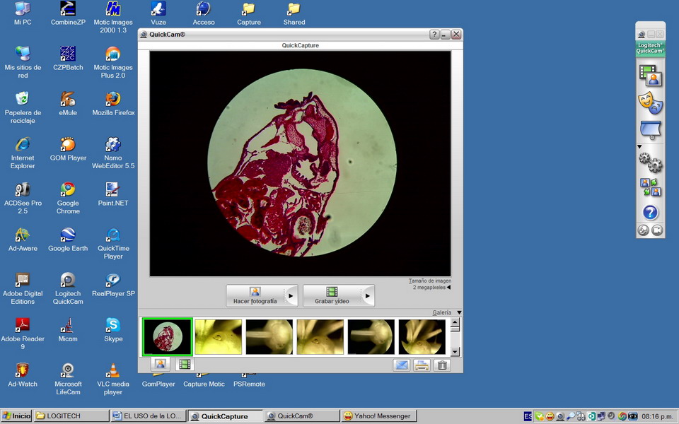
Fig 17 - To the right of "desktop" is the vertical
command bar of the camera. The commands usable for the photomicrographic work are the first (an icon with
2 overlapping frames), which displays the viewer when clicked on, and the fourth
(a 2-gear icon) which open the capture tools dialog box.
Movies
can be taken even to 1600 x 1200 px but if the objective
is the publication on the network they must be limited to 640 or smaller sizes
due to the file size in MB that is quickly reached for a few seconds video. Below the
command buttons, is the "images ribbon" containing a
"thumbnail image of captured pictures. The last captured image appears to the
left on the ribbon.
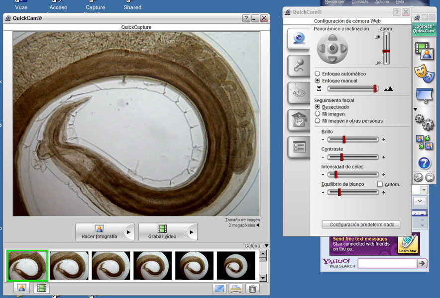
Fig. 18. The viewer with deployed control box.
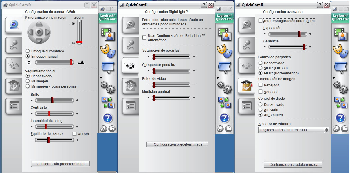
Fig. 19 - Controls are contained in three easily accessible boxes.
The control screen can now be
closed or left open at will, but the rest of the work continues on the monitor
screen as seen above.
All still images presented
earlier have been taken in bright field.
With a large
capture size selected (1.3 Mpx upwards) the picturess are not recorded instantly as with
the DC3 software, but a second later, which is a serious problem to manually
register a short series of still photos of mobile objects. This will be examined
in a later section.
1) The camera
produces only .jpg files. Set
the capture quality to 100%. A click on the arrow to the right edge
of the "Capture Image" button, opens a dialog box, select 100%
quality.
2) Use neutral
density filters to adjust lighting. To decrease the voltage changes the color
temperature. Verify
that the intensity of light is correct. If the
light is insufficient the image background
shows micro-fluctuations of the light, which translate as pixellation. Pay close attention and increase the
light until it sets.
3) Adjust the capture parameters with
the camera software.
4) You can take
snapshots, especially with stationary objects. A picture of 2 Mpx requires a second
to register. At
960 x 720 registration is a few tenths of a second. Remember that "2 Mpx"
really means an 800x600 picture (if it is not zoomed)
5) However, to use
with Combine Z, and especially with moving objects, it
might be better to take a
High Resolution (960
x 720) video. I've made even acceptable ones, at 10 fps, with a size of
1600x1200.
UTILITY OF DIFFERENT
SIZES OF CAPTURE
ENLARGEMENT TECHNIQUES
Just
like the DC-3, this camera provides automatically (if it were so programmed) images
expanded by its internal software (DIGITAL zoom).
|
|
|
|
|
|
|
|
|
|
|
|
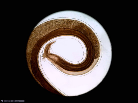
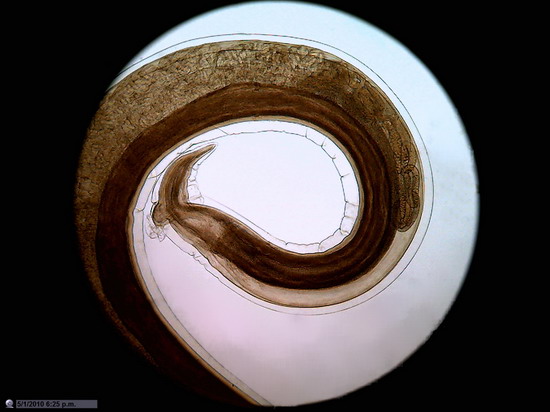
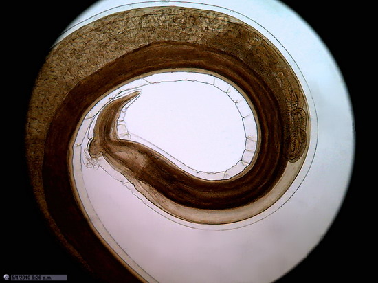
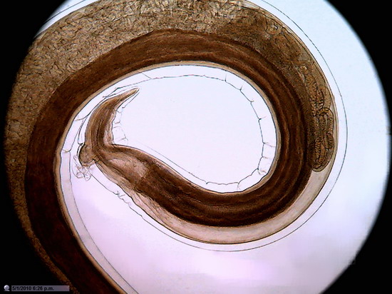
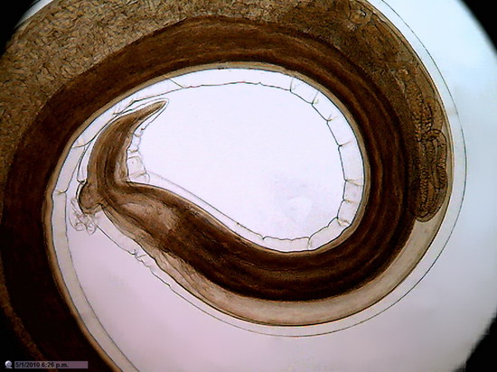
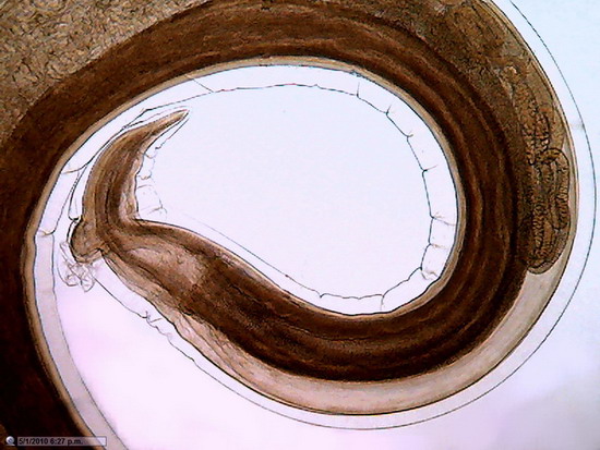
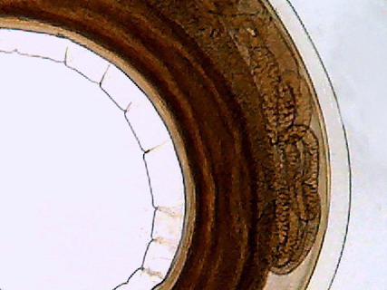
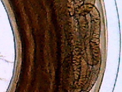
Figure 20
The first six
pictures (a to f) were obtained by changing the Size Selector (in the Capture
Screen) to get pictures of 2 Mpx
(1600x1200) and gradually sliding the zoom cursor (Command Box 1) to increase the apparent size
of the picture. Of course all the pictures have the same optical
resolution (corresponding to the 10x objective (NA 0.25) through which they
were taken). The first image covers exactly the corresponding 0.8 mpx. The
following pictures appear to be gradually covering the sensor. However,
since the camera lens has still exclusively 3.7 mm focal length, and this is
not variable, the pictures are just an augmentation of the first digital photo,
all included in a framework limited to 1600 x 1200 px.
To
make visible the process explained above, I reduced the pictures to include them
in the table. That's cheating on the quality of the reduced images, which seem to
have all a good digital resolution.
Pictures 7 and 8 are 1:1 crops of the 1st. picture (not zoomed), and of the 6th. picture
(total coverage zoom) respectively. In this case the highest
zoom
produces a disastrous effect. The
pixellation destroys all significant detail of the 0.8 Mpx. It's not worth it to use the
zoom to that power.
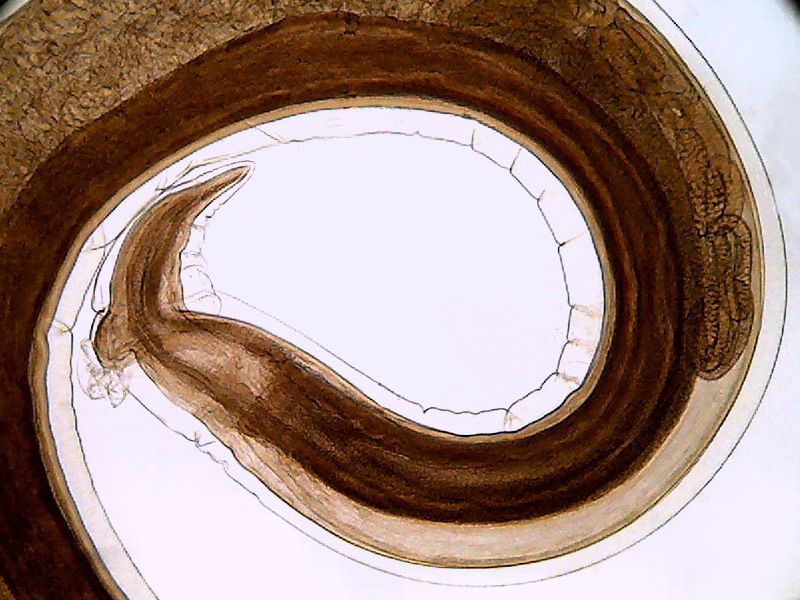
Fig. 21 - The above image is a crop to 800 x 600 of the
first image of picture 20 (0.8 Mpx. without Zoom) that as can be seen (and understandably)
covers the same Visual Field that the photo with the maximum zoom, but is of
acceptable quality, and of a size suitable for normal publication online.
However it should be noted that spiral thin lines of the subject shows a stepped
line (aliasing) that I could not remove by any technique at my fingertip.
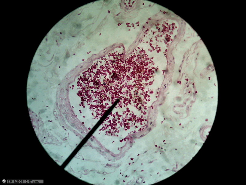
Figure 22 - Image of the entire sensor with 1200 px diameter circle (1.3 mpx surface), which is already a zoom of 20% over the normal circle of diameter 1000 px (0.8 Mpx). 10x Objective. Blood vessel in the duodenum section. Reduced to 800x600px
Not that I have an
obsession with blood vessels, but the presence of many small discrete objects
of strong color and net shape make them suitable for these tests.
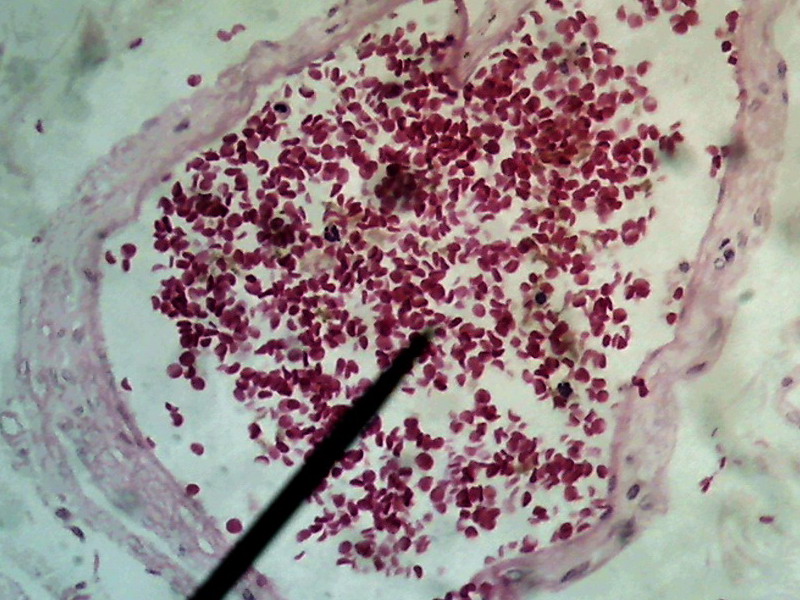
Figure 23 -
1:1 Crop, 800 x 600 px, cut from the center of the original of above image . The
maximum rectangle inscribed in the circle of pict 22 (original) would be one of 1000 x
750
px.
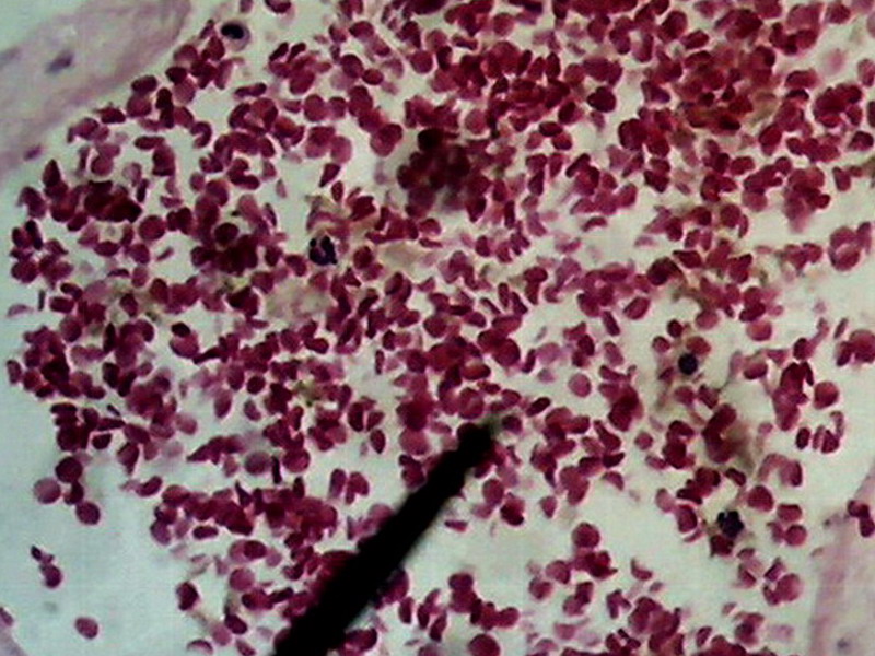
Fig. 24.
Previous image was expanded with Lanczos in 10 successive steps from 800 x 600 to
1600x 1200, and, then, trimmed again to 800 x 600 for inclusion here. No further treatment except resizing
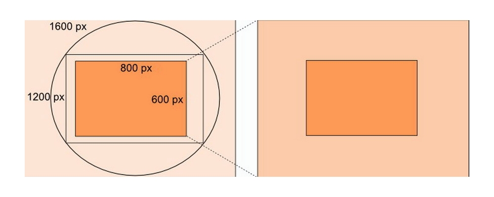
Fig. 25 - This is a diagram of the process I applied to obtain pict. 24, here represented by the orange rectangle at right
The choice of the enlargement method, if this seems desirable to apply, depends therefore on the subject. We must experience which option gives better results.
HOWEVER AND WHENEVER POSSIBLE, IT IS BETTER TO REMEMBER THAT THE MICROSCOPE HAS SEVERAL OBJECTIVES.
The best enlargement, because it is the
product of the best optics with
appropriate NA, is provided by the microscope. While "empty
enlargement" may have a lot of sense, as we saw earlier, its better not
to abuse of it.
Reduction
of noise and moiré.
Taking pictures in light-limiting conditions,
especially, generates images with "dust" or "noise". All image processing software
have commands to remove noise. But
even if they could be tested, if there is no other option, to select the best
available, none has worked so well for me as the free NetImage Demo.
Apart from the noise the other major annoyances are
the aliasing and "moiré" (pronounced "more-ay"). (usually there is a "remove
moiré" in the "Effects" menu of the Pictures Editors)
If
this sounds unfamiliar to someone (which seems difficult in this era of digital
image processing) they can use these link to better understand the picture problems
and the picture
enhancement techniques
http://www.cambridgeincolour.com/tutorials.htm
THE
DEPTH OF FIELD
A concern of any
photomicrographist is that the subjects under observation have thickness (sometimes
important), and the FIELD of VIEW has in turn its own thickness "Depth
of Field" (more, equal to,
or less than the subject as is the case). And, also, each objective has a "Depth of Focus",
i.e. you can directly browse a slice of the environment (or the subject) which
has only a limited depth.
It is known that the microscopist overcomes both
problems because it has the tool of manual "Focus adjustment" and the mental
capacity to synthesize his data conceptually quickly and efficiently, while exploring
the different levels. The
process is highly unconscious, and the microscopist thus acquires their notion of
the spatial structure of their subjects under observation.
But when you take a picture this will only cover the Depth
of Focus. The
rest, above or below, will be blurred.
In recent years several digital programs have tried to
solve the problem, "adding" the well focused parts on each of a
series of successive planes, recorded by the camera as separate images. I use, because of its
effectiveness, and the constant support offered by its designer, Alan Hadley,
against every difficulty find by anyone, the CombineZP software, which is also
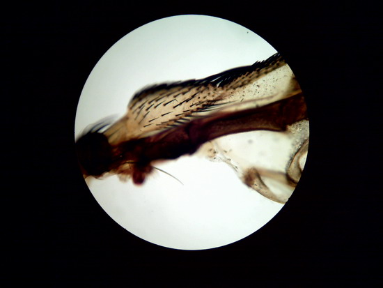
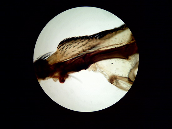
free. The
following is an image reconstructed from the amalgamation of pictures of an
area near to the joint of the wing of a fly.
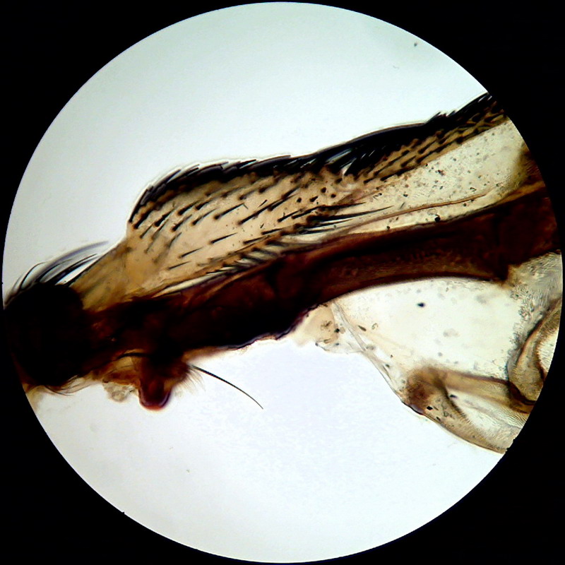
Figure 26
Wing of "Musca domestica. Stack of
5 images amalgamated with CombineZP. Without
post-processing.
|
|
|
|
Figure 27 First picture in stack |
Figure 28 Last picture in stack |
CONCLUSIONS
One
of the nice features of this camera is that, even with low light intensities
(and even disabling the Right Light control, which generally only produces problems) the sensor
has sensitivity enough to record images with all objectives of the system, including
the immersion 100xOI
objective.
In principle we can say that the camera will be useful
for bright field microscopy, for any fixed and mounted subject in a thin
preparation. Even with the afocal techique, and certainly better
if used with an appropiate relay lens to allow a full coverage of
the sensor. Bacteria, hematology,
animal and plant histology, and any other microscope slide (the so-called
"permanent preparations" of any type, eg micro-arthropods or
arthropod parts).
Other appropriate subjects include foraminifera, radiolaria, desmideacea, filamentous algae, many chloroficean and cyanobacteria, entomostraca, hidracarina, tardigrades, slow moving worms, and any other microinvertebrate that could be anesthetized or fixed with appearance of life; Monogononta rotifers which can be clasified contracted, probably tecamebae even alive, and all protozoa that can be numb or fixed with vital appearance.
Review my article on
using the diluted formol to stop or at least slow down the microinvertebrates
for this purpose, in order to understand the technique.
http://www.microscopy-uk.org.uk/mag/artjul02/wdrelax.html
Olivier Barth (in some postings on the Forum Mikroscopia
and in Photomicrography) states that
he uses Lugol for the same purpose and
seemingly with the same technique. This option is preferable
because it is much less toxic than formaldehyde (and Lugol is probably easier to get)
In the article - Part 3: Technical notes for the collection and study methods for
bdelloid rotifers (and other aquatic microinvertebrates)
- there is an overview of many anaesthetics that can be tested on all
microinvertebrates.
http://www.microscopy-uk.org.uk/mag/artnov08/wd-rotifer3.html
Unfortunately for me, and other microscopists, with the same or similar equipment, the bdelloids, many protozoa, and the micro turbellaria, which are restless and almost impossible to anesthetize, remain intractable subjects with these types of cameras. We must wait to be able to install a flash to stop their elegant evolutions.
The third part of this article will describe the result of using some different lighting techniques with the Logitech; the use of the camera to photograph living subjects; and the posibility to make videos at various alternative sizes