Many amateur microscopists have a computer, but perhaps dont have an electronic camera linked to their microscope, as is the case with the fortunate ones I refer to in my September article.
Notwithstanding this, they could have an interest in acquiring a permanent image of the observed subjects. Or they could want an estimation of their size.
They have three options: to use a camera lucida, a drawing tube, or an eyepiece grid. For pictures of this equipment see the September article by the author in the Micscape Library. See also Roy Winsby's article on the utility and use of both grid and camera lucida.
It is possible to think of making a home made camera lucida, I have seen more than one fine example (and in the past I've made one myself; not so fine, but a working one, and one that, contrary to Roy Winsbys statement could be used by a right-handed or a left-handed microscopist). But it is really many times more difficult to make a camera lucida than a grid, it offers only a little more accuracy (but only if it is used by a trained and skilled microscopist), and is more difficult to use.
In his April 2002 "Topical Tip" Dave Walker describes the eyepiece reticles and grids and several of its many uses (including calibration to measure objects), and advice on some tips to obtain one. If you havent read it, you must do it now.
If you are as fortunate as him, you dont need my help. But in many countries and more cities, it is very difficult to find an antique shop, a dedicated secondhand scientific supplier, or even a "flea market" to search for microscopy materials .
Also Larry Jenkins published a method to prepare an eyepiece reticle aimed at measurements but not drawing, and a method to precisely calibrate it.
The methods that I want to summarize here are mainly aimed at drawing. But I don't resist the temptation to include some tools to experiment with measurements and calibration. With the help of all the above cited articles any amateur could adapt these grids and the reticles for his particular interests.
I started
writing this article thinking of describing the methods to design a grid
using Corel Draw®, or other drawing program.
A grid on the master sheet - downloadable below. |
But, I thought, if the reader has to go over all that work to make the samples, why not share my results? Therefore I describe the steps to do the job in some detail.
Don't try to use the high dots per inch printers or laser printers. They are useless for this special type of work; I've tried them. At the magnifications we must work at, the size of the dots viewed through the eyepiece is excessive. Of the several methods tried I ended up sticking to the one I used for my first homemade grid.
Some 50 years ago I used the macrophotographic stand we had in the Biology Department of my Faculty using Kodalith, a special film purposely designed for the printing business, to take a picture of a grid I drew with pen and ink. The film provides a negative with a very dark background and very clear and sharp lines. I made a contact copy of the negative on the same film, and voila! I became the proud owner of a drawing grid for the eyepiece of my Koritska microscope (it was very new in those days).
Kodalith is still on the market, but now it is sold only in bulk, for industrial use. So it is better for you to buy a professional grid or two for the same price.
There is another
high contrast industrial film from Kodak (Kodak Technical Pan Film 2415)
sold in 36 exposure cartridges; from its specifications it must be useful,
but I have no first hand experience with it. There are also "positive films"
by reversal of the negative image.
So, you may
ask, what are the steps to make my own DIY grid? If you don't have access
to equipment similar to which I had, or don't wish to try the Technical
Pan, which requires a dark room, developer, fixative, and so on, the best
option is to have recourse to the commercial photomechanical shops
that provide negatives for offset printers. The second option is to locate
the Xerox Copycenter in your city or town. (See
footnote for clarification of the services italicised).
The results from these two routes have differences that count. The photomechanical shops give you a line drawing of black lines on a very clear background. A Xerox Copycenter provides you with copies on an acetate base that have a somewhat dirty background with small speckles of carbon. In reality this does not prevent you from doing a good drawing, but you'll certainly want to remove the grid from the eyepiece to make any critical observations.
Moreover the Xerox Copycenter service copes very well with the reduction task we need which not all the photomechanical shops can do. Seek their advice, because some of the photomechanical shops have modernised and have acquired Xerox equipment. If you do go to a print shop make clear that you require a silver film based negative (and positive) not a photocopy.
Normally they have the capacity to give you a negative that is 80% reduced from the original you provide. That is, the negative would be only 20% of your original, and this reduction they accomplish automatically and with extraordinary precision. (Of course for double the price they can make for you the positive copy you really need. The Xerox Copycenter provides you directly with a positive.)
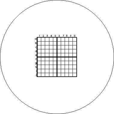
What you need is a positive grid that fits inside your eyepiece, resting on the field stop. In the old eyepieces with a narrow field of view, the field stop is more or less 0.9 or 1 cm in diameter. Your grid must therefore be 6 - 7 mm (including letters and figures) across to sit within the hole. And the interior of your eyepiece tube is probably ca. 20 mm. To suit these dimensions you need a master grid 3.8 cm in size centered on a circle of 10 cm (20% of 10 = 2). See the original below which I provide for download. The lines have been drawn 0.2 mm wide, so that the thinnest ones are clearly visible, although somewhat grayish perhaps, when the positives are done. Give the processors your diskette and ask for a reduction to 20%.
Now for the "extras" provided on the downloadable sheet below.
The photomechanical shops charge you for a "reduction". The minimum negative they produce (at least in Durango) is 11 cm x 14 cm (154 square centimeters). You have used 4 square cms for your grid, and have lots of film surface that you can use for other negatives and positives; so be creative.
In the original that I offer for download, I include the drawing grid, another grid that can help you make censuses of microscopical populations (I will explain in a future article how to make censuses, and explain why), a protractor to measure angles on your critters, and two rules (reticles) to experiment with calibration and measurements. I use the word rules to emphasize the difference between our homemade tools and the professional ones.
Don't worry about cost. The reduction has a fixed price. In Durango it amounts to U$2.5 - $3. You must expend U$5 or U$6 to for both the negative plus the positive to obtain four near-professional quality tools and an experimental one. The Xerox Copycenter service, at least here, doubles the price, so your "reduction" positive costs the same.
It is not a bad deal. Really it is a gift if you realize that all five professional tools cost more than U$400.
Of course you must add some work and materials to finish your tools.
With a very sharp and fine pointed scissors cut your discs of film and see how they fit in your eyepiece tubes.
As the film base could be thin and with time may not remain flat, you can support the margins with a rigid ring. An aluminum or copper wire could be fitted on the eyepiece tube, cut, and closed to make the ring. Be sure that the ring fits in the tube without excessive friction.
Spread a little epoxy adhesive on the ring and press it onto the disk of film. Dry completely under a weight. Verify the film is on the underside of the ring and could be applied over the eyepiece field stop, and that the grid has the proper orientation to be seen upright when it is in its working position.
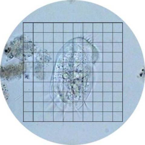
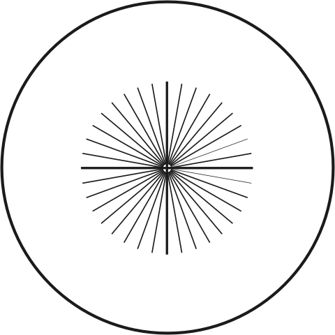
Slide the mounted grid to its working position in the eyepiece tube, and screw-in the front lens. Look down the eyepiece of the well-lit microscope. You must see your grid clearly, more or less as in this fake microscopic field of view (fig 2). Perhaps you need to make small adjustments to the eyepiece orientation. If this is the case, when you are satisfied with the setup, put a drop of school paper adhesive on the rim and allow to dry. The front lens could be freed easily if the needs arises.
To use the grid to draw, it won't need any calibration. Follow the instructions
in Roy Winsby's article.
If you have a more modern microscope, with a new generation of wide field eyepieces, you may, as I did, have a surprise. In my eyepiece with a field of view of 18 mm the grid floated in the void. If you have a digital camera linked to your microscope you best have recourse to the tools and methods I summarize in my previous articles on drawing microscopic subjects. But if you don't, download this second original that I have drawn for you. When mounting time arrives it is possible that you, like me, must mount your disk not between the lenses, but under the lenses. Pay attention to the orientation of the reticle and a convenient position for the supporting ring. Also be prepared to make a supplementary ring with some scope for expansion (make it a little oversized with a small gap to allow for adjustments) to help the grid remain in position.
APPENDIX
Click the images to download the two master sheets in Acrobat® pdf format.
For non wide field eyepieces. |
For wide field eyepieces. |
The other tools on the downloadable sheet make it possible to accomplish many interesting tasks.
 The PROTRACTOR is a circle with lines covering 360º increasing at
10º intervals. With it you can estimate the angle subtended by two
converging lines of a microscopic subject.
The PROTRACTOR is a circle with lines covering 360º increasing at
10º intervals. With it you can estimate the angle subtended by two
converging lines of a microscopic subject.
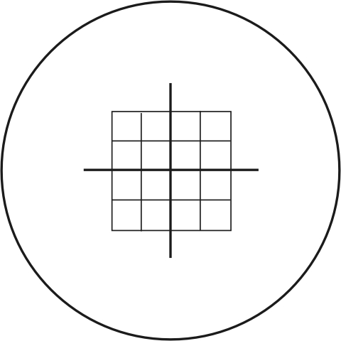
The QUADRANT SQUARE is used mainly to count items, to estimate the number of them in a sample. Its use is subject to certain rules that I will explain in a future article, probably some months ahead.
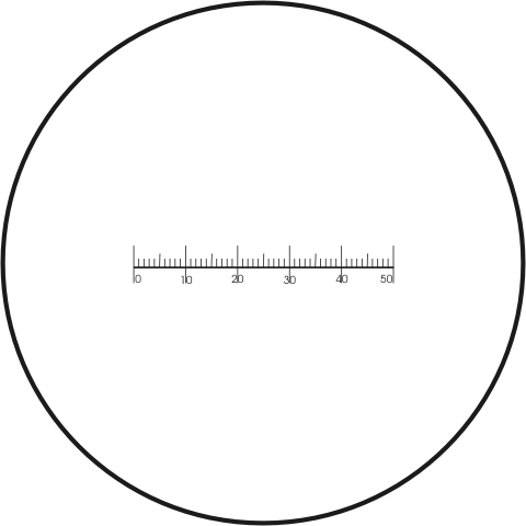
 The EYEPIECE RULE is designed specifically to help you to measure your
microscopic subjects. You must calibrate the reticle against a standard
placed on the stage. The best and professional one is a micrometric
scale, that in the long run if you are
a serious and dedicated microscopist, you must buy (its price is in the
order of the U$ 80.oo - 100.oo) But for the time being I include the STAGE
RULE of 5 mm divided in 100 micrometers intervals, for you to make calibration
trials.
The EYEPIECE RULE is designed specifically to help you to measure your
microscopic subjects. You must calibrate the reticle against a standard
placed on the stage. The best and professional one is a micrometric
scale, that in the long run if you are
a serious and dedicated microscopist, you must buy (its price is in the
order of the U$ 80.oo - 100.oo) But for the time being I include the STAGE
RULE of 5 mm divided in 100 micrometers intervals, for you to make calibration
trials.
For
the protractor,
the square,
and the eyepiece rule,
follow the suggestions to mount the eyepiece
grid, so you can use one of them when
you need it. If the downloaded original is neat and clear, and the negative
and positive are made with care you can be confident that your tools are
very nearly performing as any professional ones.
For the stage rule you require three copies. Or more. (Of course you can order two or three copies of the original in your "reduction".) Inspect them with the low and medium power of your microscope, select the best one, with the more narrow lines, more equally spaced, and mount it centered in one slide, with its long axis parallel to the slide long axis. If you have Canada balsam this is the best choice. Or you can use nail polish or fructose. I recommend the nail polish, put a little drop of medium at the slide's center. With fine pointed tweezers apply the rule over the drop. With care apply some pressure on the rule and leave alone for some 30 minutes to allow for the nail polish to dry and fix the piece of film in position. Now apply some supplementary drops of media around and over the rule, and another on a coverslide. Cover, and allow the media to reach the borders of the slide. Leave to dry and finish. I mounted another copy in another slide, but perpendicular to the long axis. You can see below some pictures of it.
The rule's original size is 2.5 cm divided in 50 half millimeter divisions. When reduced it must have a total length of 5 mm. Any one division must be 100 micrometers.
The professional micrometric scales have a 1 or 2 mm span, intervals of 10 micrometers, and very fine and sharp engraved lines. Of course the appearance of your stage rule cannot compete with these masterpieces. Moreover, if the scale was reduced with care, and you insisted to your print shop operator to check the length was really 5 mm, it is really possible that your divisions would be of 100 exact micrometers. This is almost half the thickness of a thin coverslip or the print from a good 2400 points per inch inkjet printer (the only other reliable and affordable standards you can have at hand, that can be 170 to 250 micrometers thick). See the articles of J.M. Cavanihac, and that of Howard Webb (in refs.).
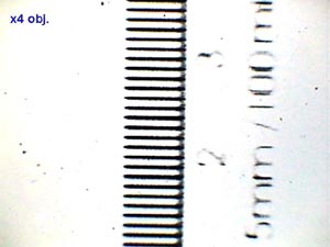
CALIBRATION.- To calibrate your eyepiece rule, put it in your eyepiece. Rotate the eyepiece to place the rule horizontal in the field of view. Now put the stage rule in position, and focus it with your lowest power objective. Superimpose the two scales so that you can make your best estimate on how many of the eyepiece divisions (E) are included in how many 100 micrometers divisions (D). D x 100/E calculates the micrometer equivalent (me) of one eyepiece rule division. For my 4x objective and the scale mounted on my 10x eyepiece, 49 divisions of the rule encompasses 24 of the stage rule divisions. So me = 24 x 100/49 = 48,98(49) micrometers.
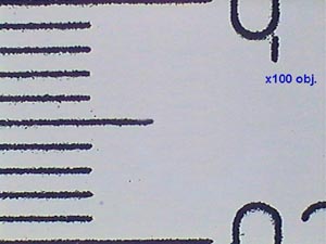
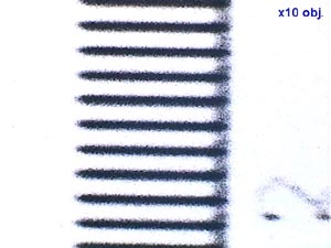
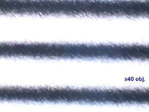
Repeat this for the other objectives you have. If you are lucky enough, even a 100X OI objective can be approximately calibrated with your photoreduced 0.5 cm rule. See the picture below. I have used a Xerox version to show that it is really useful.
For my 10x objective the estimated value was 20 micrometers, for the 40x, it was 5, and for the 100x, only 2 micrometers.
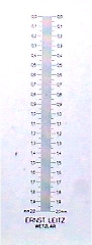
As I thought that there could be some inaccuracies because in view of the other values the 4x ought to be 50, I checked the estimations with my Leitz Wetzlar micrometer stage. The values that I must consider most accurate were: 4x = 48.90, 10x = 19.56, 40x = 5, 100x = 2. With an error of 0.2% I can consider these values as 50, 20, 5 and 2 .
TAKING
MEASUREMENTS.- Now, to calculate the size of any microscopic object,
select the objective that gives the best and most comfortable view, the
bigger the better, and line up the object to the rule. You can rotate the
eyepiece to better fit the object orientation. Estimate the number of divisions
(N)
(and fractions of them if necessary, it is easy to estimate a half of the
lesser division) of the rule that comprises the object.
N
x me gives you the estimated size of your
object.
You can use the same method to calibrate also the drawing grid, this could help to make a gross size estimate of something you are drawing.
The STAGE RULE is really the only feature not comparable to a professional tool. The lines are coarse and somewhat dirty. Observe your rule and check that the 100 micrometers intervals are a consistent size. When making a size estimation at low power put the first line of the eyepiece rule on the outside border of the first line of the stage rule. Search for the coincidence of some other line of the eyepiece rule with the outside border of any other stage rule line. Count the intermediate intervals. At higher powers it may be more accurate to use as reference points the mid-point of each line. Count the intervals until you have another match of a line mid-point. As always repeat your estimation in another position of the rule and take the arithmetic mean. There are some small inaccuracies on the width of the lines and intervals, but really they are minor ones.
BECAUSE.....
I have measured with professional equipment the tools that my print shop made for me, Of course as I had insisted before, only the stage rule could be questioned. But I assure you that my Leitz Wetzlar micrometer stage rule gives me almost exactly the same results I obtained with this DIY rule.
As
you can imagine, the DIY rule can also be used by those that have a digital
camera but do not have a stage micrometric scale. For details see my article
on meters
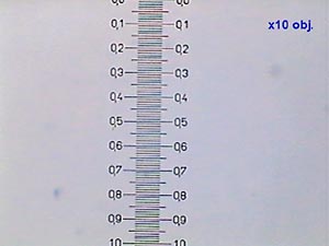
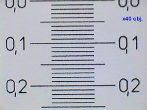
and measures. The following pictures show
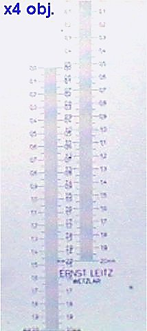
the aspect of both the DIY rule and my Leitz stage micrometer. As you can
see the DIY is more efficient than the Leitz, to measure the width of the
field of view of my digital camera at low power. To demonstrate the real
width with some accuracy I must make an amalgamation of two pictures of
the Leitz with the x4 objective. For the other powers you can see that
is very easy to estimate the real value. In the DIY scale that I mounted,
the line and void of one interval equates to three line widths. Now, the
line is 33 micrometers wide. Using care and the anterior data I made
these field of view estimations with the DIY rule and the Leitz one:
Objective Leitz DIY Error
4x
2530
2533 +0.12%
10x
1015
1010 -0.49%
40x
260
260
0
100x
100
100
0
You
can make your own estimation with these actual pictures. I am sorry, the
results are so good that I think they could be doubtful to some. Please,
give the originals to your Xerox copy shop and try the tools yourself.
 |
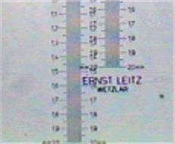
Left image: camera's
full image width and micrometer rule (4x objective).
|
 |
 |
 |
 |
 |
 |
 |
 |
I would very much like to hear of the results obtained by those who try the methods outlined above.
Comments to the author, Walter Dioni, are, welcomed.
Footnotes
Photomechanical
shop - is a service where they prepare the photographic films or negatives
that are used to make the engravings (printing plate) that are later used
by a printer.
Xerox Copycenter - is where they photograph the 'originals' with a 'filming machine', then make the reductions, and later produce the positive that they give to you. But it is not a photocopy reduction (which many copying shops offer), but specialized work.
If these exact named
facilities aren't available locally, have a chat with the local printers
/ printing shop / copy shop to see what service they may provide which
corresponds to the above. Return
to article.
REFERENCES
Dioni, W. - About microscopes, measurements and meters.
Dioni, W. - Drawing your microscopic subjects. Part 1.
Jenkins, L. - Topical Tips 10 - Printing a calibrated rule.
Walker, D. - Topical Tips 9 - The versatile eyepiece reticle.
Webb, H. - A " good enough" stage micrometer.
Winsby, R. - Drawing through the microscope.