5. GEOMETRIC MICROSCOPE OPTICS
The laws by which light rays are broken (refracted) by lenses are called geometric optics. A lens is a piece of glass where the surfaces are not parallel, but one or both are either:
- convex: a positive lens, or
- concave: a negative lens.
The perpendicular line through the
center of the lens is called the optical axis.
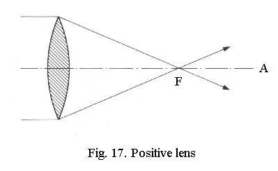
A positive lens (Fig. 17) concentrates
parallel rays of light from infinity (e.g. the sun) in a point called the
focus.
Thus, you can project an image of the sun on a piece of paper held at the
focus. If you run the rays in Fig. 17 from right to left instead of from
left to right, youll find a second focus, at the same distance from the
lens in this case. Theres a front focus and a rear focus, therefore:
F1 and F2.
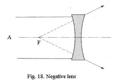
A negative lens (Fig. 18) has a virtual
focus - parallel rays are made to divert and seem to come from
a focus on the other side of the lens. Thus a negative lens does not project
an image on a piece of paper.
The distance between the focus and
the center of the lens is called the focal length.
Focal planes
Project an image of the sun on a
piece of paper by pointing the lower (larger) field lens of an eyepiece
at the sun. An image is not formed in a point, but in a plane, called the
focal
plane. If you turn the eyepiece around (smallest lens pointing at
the sun), no image can be formed. The front and rear focal planes of a
lens system therefore may have totally different positions.
Two rules
Two simple rules are sufficient
to understand what lenses do:
A ray from infinity, which runs
parallel to the optical axis, is refracted through the focus. Conversely,
a ray from the focus always exits the lens parallel to the optical axis.
A ray through the center of the
lens is not refracted but goes straight through.
In ray tracings, lenses are always
reduced to simple lines, which Ive marked L in the drawings.
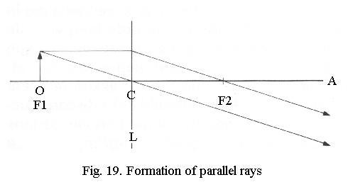
If you place an object at the front
focus of a lens (Fig. 19) and apply the two rules (ray through center goes
straight through, ray parallel to optical axis goes through rear focus),
youll find that all rays exit the lens in parallel. The object seems to
be located at infinity.
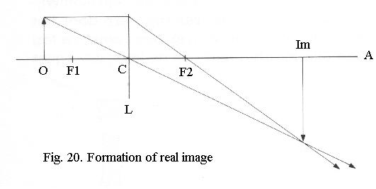
If you place the object further away than the front focus (Fig. 20), application of the rules results in a projected image that is upside down. This is called a real image because you can see it on a screen.
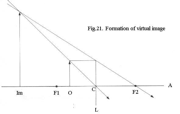
If you place the object inside the front focus (Fig. 21), you get a magnified image. Its in front of the lens so you cant project it and therefore its a virtual image. The lens now acts as a magnifier.
Light
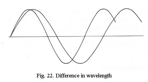
Visible light consists of electromagnetic
waves with a wavelength (Fig. 22) between
about 780 nm (red) and 380 nm (violet). A nanometer (nm) is 1/1000 micrometer
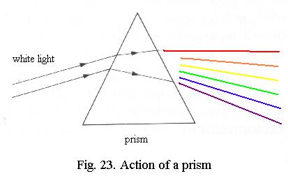
(µm), which in turn is 1/1000 millimeter (mm). White light is a mixof all colours, as is shown by sending it through a prism (Fig. 23), when
it is split into a spectrum.
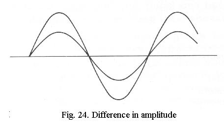
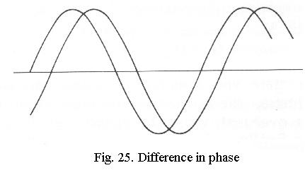
Besides in wavelength, two light waves can also differ in amplitude (Fig. 24), which we interpret as a difference in brightness, and in phase (Fig. 25), when one wave is delayed in relation to the other. The human eye cannot distinguish phase differences.
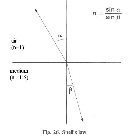
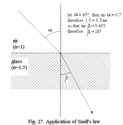
Refractive index
If you partially submerge a stick
in water, the stick appears to be broken. This is because light rays passing
from one medium into another are refracted
- deviated from their original path. The degree of this deviation depends
on the refracting power of the media, called refractive
index and given the symbol n. Some values:
- air: n = 1.0;
- water: n = 1.33;
- window glass, immersion oil: n = 1.515;
- special glass types: n = 1.45 to 1.95;
- Canada Balsam ( microscopy mountant): about 1.5;
- naphrax (mountant for diatoms): 1.74.
Dispersion
The refractive index of a medium
is not constant for light of different wavelengths. This is why a prism
disperses white light into a spectrum: for red the refractive index is
lower than for violet. Dispersion varies greatlyfor different media, independent of their refractive index.
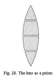
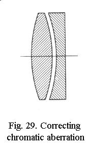
Chromatic aberration
A lens can be thought of as a series
of prisms (Fig. 28) and thus also splits light into its constituent colours.
The focus lies closer to the lens for blue than for red light, so there
is an overlapping series of images of different colours. This is called
chromatic
aberration. Because a negative lens has an effect opposite to that
of a positive one, the chromatic aberration of a positive lens can be corrected
by combining it with a weaker negative lens made of glass with
a
much greater dispersion, Fig. 29. The lens thus remains positive
(so it magnifies) but the dispersions counteract each other.
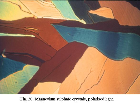
Such lenses are called achromatic and produce good images, but the colour correction is actually only optimum in yellow and green. Near the orange and near the blue it becomes less perfect. By using special types of glass, the residual errors can be further suppressed and such lenses are called fluorite objectives and apochromats. They yield sharper and more contrasty images also in the red and violet and as a rule also have a higher numerical aperture. However, do not underestimate the performance of really good achromats - they even permit colour photomicrography (Fig. 30).
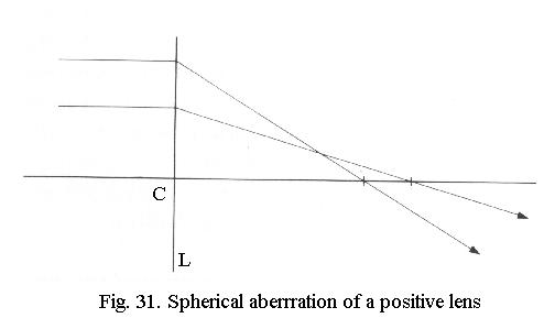
Spherical aberration
If Snells law is used to construct
the ray paths of central and peripheral rays through a lens, the focus
for the central rays is found to lie at a different position from that
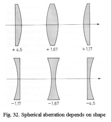
of the peripheral rays (Fig. 31). This is spherical
aberration and Fig. 32 shows that its magnitude strongly depends
on the shape of the lens, with negative lenses again showing values of
opposite sign. Correction can be done by combining a positive lens of a
shape that has a low value of spherical aberration with a much weaker lens
of a shape that has great but opposite spherical aberration. As you may
suspect, this spherical correction is again colour-dependent; for achromats
it is good in yellow and green, for fluorite lenses and apochromats its
also good in both the red and the blue.
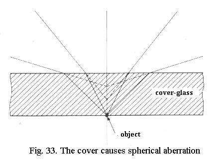
Effect of cover-glass
Light rays from the object do not
exit in parallel beams, but as a cone or fan of beams, as well see
further on. The object lies on the lower surface of the cover-glass (Fig.
33) but when the light rays leave the top of the cover-glass (before they
enter the objective) they pass into a different medium (from glass to air)
and are refracted. This results in severe spherical
aberration: for rays that leave the object at a large angle the
object seems to lie higher than for rays that leave the object at a small
angle.
To counteract this, objectives need to have a strong built-in negative spherical aberration, in other words: the objective is given a strong intentional error. If such an objective is used without cover-glass, the full built-in spherical error will come out! As the spherical aberration caused by the cover-glass depends on the thickness of the latter, objectives are mostly corrected for a standard cover-glass thickness, of 0.17 mm. The effect of incorrect cover-glass thickness is worse as the numerical aperture of the objective is higher and it becomes objectionable above NA 0.4 or so. With a dry objective of NA 0.95 (a typical 40x apochromat) a difference of 0.2 mm in cover-glass thickness seriously impairs image quality! For uncovered specimens (e.g. in mineralogy) special objectives are made, showing d = 0 on the mount. These, of course, are useless for covered specimens.
The correction of the combination of cover-glass and objective for spherical aberration is also affected by the tubelength, which is why this could be adjusted in vintage stands. At present, tubelength is fixed. In that case, the degree of spherical correction of high-power objectives can only be adjusted if the objective has a correction collar, which alters the relative positions of lenses within the objective. This adjustment is done on the basis of the image quality attained and therefore requires considerable experience in assessing image quality.
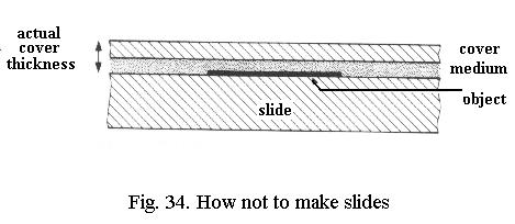
Preparation errors
Cover-glasses of good quality specify
the thickness on the box and vary only between narrow limits. But you can
ruin the entire situation by incorrectly preparing a slide!
If you place the specimen on the slide and then put a cover-glass with mountant on top of it, you get the situation of Fig. 34. Regardless of whether the cover-glass is of the correct thickness, youve added an unspecified but considerable thickness of mountant to it, resulting in severe spherical aberration. Always place the specimen on the lower surface of the cover-glass, never on the slide!
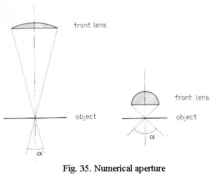
Numerical aperture
As weve seen, high-power objectives
have a higher NA than low-power ones and this results in greater resolving
power. If we draw a low-power objective and a high-power one (Fig. 35),
its clear that the latter catches rays under a greater angle. This angle
of admittance determines the NA of the objective as follows:
NA = n * sin u
in which n = the refractive index of the medium in front of the lens and sin u = the sine of half the angle of admittance. As the angle of admittance can never be greater than 180° (the rays would then return) and the sine of 90° (half of it, u) = 1.0, the NA is always less than 1.0 if there is air in front of the lens, because for air n = 1.0. Higher NA, or higher resolving power, cannot be obtained by increasing u to an arbitrarily high value.
Immersion objectives
But it can be increased if n in
the formula is raised, and that is done by dipping the front lens of a
specially constructed immersion objective
into a liquid. In the majority of cases, this is a special immersion
oil, whose refractive index (n = 1.515) and dispersion are the same
as those of the cover-glass and the objectives front lens.
That immediately implies that the
spherical aberration caused by the cover-glass is also absent (its like
there is also glass between the cover and the front lens!), so that cover-glass
thickness is no longer critical. The objective becomes easier to construct
because it need not have a strong built-in negative spherical aberration.
The NA then attainable is 1.25 to 1.4.
There are also water immersion
objectives, although these are rather rare. Ive found medium-power (40
- 50x) water immersions very useful as their performance is much better
than that of a dry objective and although it is slightly inferior to
that of an oil immersion of the same power, removal of the water (just
touch with tissue paper) is much easier than removal of oil. This makes
it simple to switch forwards and backwards between a 40x immersion and
a dry 20x or 10x objective. The NA of water immersions is about 0.85
to 1.0 for medium- and 1.2 for high-power objectives.
«««« »»»»