The laws by which fine detail is made visible in an optical instrument are called physical optics. The reason why physical optics are quite different from geometric optics is that light consists of waves (not straight arrows as geometric optics treats them) and are affected by the object. Ray tracings are fine to show where the image lies, but they do not yield information on the properties of the image. Well assume that the quality of the objective is perfect so that performance will not be impaired by serious aberrations.
Image formation
The theory of image formation was
formulated by Ernst Abbe in the late 19th century. Abbe treated the
object as a fine grating and although that is not an exact description
of say, plant sections, it is a very good approximation of the regular
structure of diatoms.
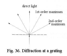
When light passes through a grating it is scattered (diffracted) so that it becomes a fan - or rather, a cone, Fig. 36. A narrow parallel bundle of light that enters the object is therefore split into an undeviated (straight through) bundle and deviated bundles on both sides. The undeviated light contains no information about the object, its simply the background illumination. The deviated light contains the objects information. The image is formed behind the lens, where the deviated and undeviated light interact (interfere).
A reasonable image can already beobtained when the two deviated bundles closest to the undeviated light
(the first-order maxima) are passed through
the objective to interfere with the undeviated light. If the higher-order
maxima are not included in image formation, the image is not perfect but
it can be seen that a grating is involved and the fineness of the grating
can be determined. That is to say: there is just sufficient resolution.
The degree of diffraction, i.e.
the angle between the two first-order maxima,
depends on two factors:
- the finer the grating, the greater the angle
- the shorter the wavelength of the light, the smaller the angle
Experiment:
Diffraction can be demonstrated
beautifully with a slide of the diatom Pleurosigma angulatum.
Focus normally with the 100x oil immersion objective, then close the condenser
iris as far as it will go. Check the aperture with a centering telescope
(the unaided eye wont do here because the image is small). A star-shaped
diffraction pattern is seen, each of the six points of the star is a spectrum
with violet inside (less markedly diffracted) and red outside (markedly
diffracted). These are the first-order maxima and this is exactly what
the theory predicts!
Because diffraction by finer detail increases the angle between the first-order maxima, its now evident why high resolving power requires a wide angle of admittance of the objective, i.e. a high NA.
Another advantage of the immersion objective can now also be explained (Fig. 37): as the angle of the diffracted image-forming rays coming out of the object increases, there comes a point where by Snells law the angle of these rays becomes 90º or more when they pass from the top of the cover-glass into the air. That is to say, they do not leave the cover-glass but are reflected backwards so that the diffracted rays representing the fine image detail do not enter the objective at all. By using an immersion lens, this total reflection is avoided and for fine gratings information-carrying rays also enter the objective.
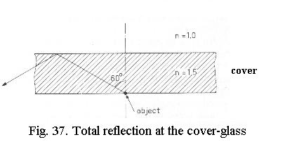
The advantages of an oil immersion objective are, therefore, three-fold:
- higher NA of the lens
- no spherical aberration due to the cover-glass
- no total reflection at the upper cover-glass surface.
The condensers contribution
So far we assumed that the specimen
is illuminated by a narrow beam of parallel light. From Abbes theory it
followed that an image results when the two first-order maxima can interfere
with the undeviated light. Actually, only one first-order maximum is already
sufficient: because it is representative for the grating, it carries just
enough information to create an image when it alone interferes with the
undeviated light. (If you happen to be a radio ham: its the equivalent
of single sideband).
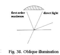
That means that if the light is made to strike the specimen obliquely (Fig. 38), both one first-order maximum and the undeviated light can be caught by the objective - the angle of admittance of the objective appears to be doubled. If you illuminate obliquely from all sides instead of from one side only, you get a cone of light at an angle equal to the angle of admittance of the objective. And that is exactly what the condenser supplies.
Weve seen earlier that in order
to fill an immersion objective completely with light, the condenser must
also be oiled to the slide. This is very bothersome, increases glare and
may so reduce contrast that you cant benefit from the improvement in resolution.
The condenser iris is (almost) never fully opened anyway with objectives
of any NA because this would reduce contrast. Only the most recent apochromats
permit full illumination of their aperture and even so, they still show
somewhat better contrast when the condenser is slightly stopped down.
Resolution
The resolution with brightfield
microscopy can be calculated reasonably well with the formula
d
= 1.22 * l
/ NAobj + NAcond
where: d= resolution in µm; l = wavelength of the light used (0.5 µm for white light as average value); NAobj = NA of the objective; NAcond = NA of the condenser. The latter is the effective NA, that is the portion of the full NA actually in use as controlled by the condenser iris!
From this formula, you can easily
calculate that the gain in resolution by immersion of the condenser (NAcond
raised from 0.95 to 1.2) is only marginal. Likewise, reducing the size
of the condenser iris to about 80% of the full aperture of an objective
only slightly reduces resolution while greatly improving contrast. The
formula shows that for light of 0.5 µm wavelength, NAobj
= 1.3 and NAcond = 0.95 (dry) the maximum
resolution the microscope can give equals about 0.26 µm. This is
the limit you can reach in routine practice.
What magnification?
Whereas weve worried a lot about
ensuring high NA, weve not yet once mentioned magnification. The reason
is that whilst ensuring high resolution is absolutely crucial, magnification
says nothing about the information content of the image. In his theory,
Abbe also treated magnification, but here he tripped up wonderfully because
he made wildly optimistic assumptions of the performance of the human eye,
as later research has shown. So dont believe older books!
Magnification is a matter of convenience and ensuring that none of the information in the image is lost. Here is how to decide on magnification, and for an example I consider a specimen that contains detail with a fineness of 0.3 µm :
Visual observation:
At a comfortable reading distance
of 25 cm (which is what we approximate in microscopy), people with very
sharp eyes can resolve 0.3 mm, others reach 0.5 mm. Magnification of 1000x
is OK for some, 1500x is better for others.
Photomicrography:
Document films as used in professional
photomicrography can have a resolving power of 100 lines per mm, i.e. 10
µm. Lets be very conservative, assume less perfect film and make
it 60 µm. Then the minimum effective magnification on the film
for 0.3 µm detail would be at least 200x. Because camera systems
mostly reduce power 2x, this would require at least 400x from the microscope.
For contact prints, the rules for visual observation apply, so print at
least at 1000x to 1500x for our example, or simply more if you think it
makes for more convenient viewing - e.g. at a larger distance than 25 cm.
Consumer-type digital cameras with 4 Megapixels and more are able to handle the information in a microscope image. A 3x optical zoom is necessary to avoid vignetting. It may be necessary to disable the autofocus function and set the camera at infinity. Save the images in non-compressed format (bmp) and only convert to compressed format (e.g. jpeg) after all image processing has been finished.
Prints in journals:
If your pictures are going to be
published, they will be printed using a fine screen. This will slightly
impair image quality so for the fine structure in our example I would suggest
at least 1500x and better 2000x. For a close-up of a relevant portion
of the image you might even use 2500x here. For a poor-quality journal
the printers screen will be coarser and you may have to use higher magnification.
- Video monitor, computers
This coarse screen situation also
arises if you show microscopic images on a video- or computer monitor.
A normal TV has only 625 lines for the entire height of the screen, a normal
computer monitor has 600 or 768 for the entire height and 800 or 1000 for
the entire width. This means that you can never
hope to show the detail in a hard copy photograph at the same picture size
on screen, you need a much larger scale and
scrolling of the picture may be unavoidable. Digital is not always better!
When scanning hard copy photomicrographs, and certainly when scanning negatives, you will have to remember what you do: many of my negatives on document film indeed contain detail near 50 lines per mm, which requires a scan with at least 1250 dpi. Because of the landscape screen format of most computers youd better rotate pictures for optimum viewing.
Conventional wisdom (Abbe) had it that horrible things happened when magnification was greater than about 1000x the NA of the objective, but these are fables. When looking through a microscope at very high magnification (say 2000x) youll notice the residual imperfections in the lenses - and the preparation! - more, the field of view becomes smaller and the image becomes darker. So the image will not be really crisp, thats all. But if you have a superb photomicrograph on negative or CDROM, you can blow it up to spectacular poster size for a presentation to let people enjoy it!
«««« »»»»