What we have dealt with so far is called brightfield microscopy, where the image formed by the deviated light is seen against the background of the undeviated light. This is the most usual form of routine microscopy. In this chapter I will discuss two alternative observation techniques: darkfield and phase-contrast, and briefly mention two others: observation in polarised light and interference microscopy.
Darkfield
If sunlight enters an otherwise
dark room through a slit in the curtains, tiny dust motes that were first
invisible are seen against the dark background because they scatter the
light. The undeviated light is excluded, the deviated light produces the
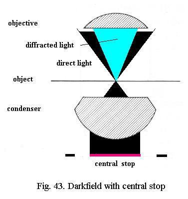
image. A simple way to obtain such darkfield
illumination is to place a central stop in
the filter ring of the condenser. This central stop can be a coin, cemented
centrally
on a plastic disc cut to fit the filter ring (CDROM cassettes are good
material).
This central stop (Fig. 43) blocks the direct light, only rays at an angle larger than the angle of admittance of the objective in use are allowed to strike the object. The backgroundis dark, the light scattered (deviated) by the object - drawn bright blue in Fig. 43 - is imaged by the objective.
The size of the central stop will obviously depend on the angle of admittance (i.e. the NA) of the objective. A central stop of about 15 mm in diameter will generally yield darkfield with objectives up to about NA 0.5, depending on the properties of the microscope condenser. A central stop of 20 mm will generally permit darkfield with a 40x/NA 0.65 objective also. Adjust the focus of the substage condenser for maximum brightness of the central field of view. The field stop of the lamp can be wide open and theres no major difference between critical or Köhler illumination.
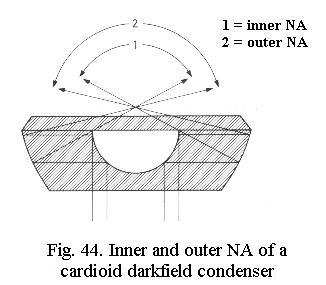
For darkfield at higher NA, special cardioid darkfield condensers using mirror surfaces (Fig. 44) are manufactured. These are oiled to the slide (instead of oil, water may be used for convenience) and require exact focusing and centering with their centering screws. Even these high-power darkfield condensers cannot be used with objectives of NA above 1.2 or higher, however. The reason is that darkfield condensers have two NAs that should be considered: the inner NA (i.e. the portion of the light that is blocked) and the outer NA (which for technical reasons is limited to at most 1.4). For an objective of NA 1.25 one would have to block everything up to at least NA 1.3 and the cone of light that would remain would thus be limited to an NA between 1.3 and 1.4. Thats simply not enough to produce practical darkfield. The inner NA limit attainable with current darkfield condensers appears to lie near 1.0 , corresponding to the medium-power (40 - 60x) oil immersion objectives offered by several manufacturers.
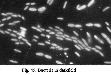
Contrast in darkfield (Fig. 45) is extreme and resolution is as high as the objective can yield. Darkfield is spectacular for observations of live protozoa or bacteria (cilia or flagella are visible) and for diatoms. I always use darkfield to scan diatom slides at low to medium power because its easy on the eyes and even the smallest and faintest diatoms stand out clearly. The limitations of darkfield:
- thick or extended objects and even dense strews are unsuitable (glare)
- residual errors in objectives (notably spherical aberration) become maximally visible. This is especially the case with a dry 40x objective and forms the reason why a 40x immersion is highly advantageous here. For examination of live specimens in darkfield a 40x water immersion is ideal.
- all specks of dirt or traces of grease also become maximally visible. You need a scrupulously clean optical train: top lens of condenser, both surfaces of slide, clean and dilute sample, grease-free object glass.
Phase-contrast
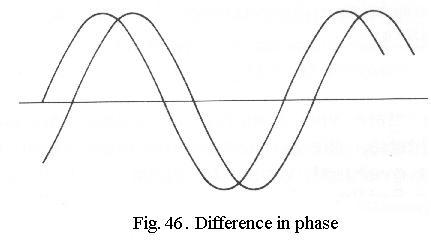
The human eye is only sensitive
to differences in amplitude (brightness) or wavelength (colour). Differences
in phase (Fig. 46) are not visible to us.
Unfortunately, many microscopic objects do not cause appreciable changes
in the intensity or colour of the light falling through them, but only
changes in phase. Such objects are called phase-objects.
Living cells and diatoms are examples.
Differences in phase result from differences in optical path length : differences in thickness in a piece of glass, for instance, and differences in refractive index (n).
The colourless silica valves of diatoms have an n slightly below 1.5. They do not absorb the light to an appreciable degree, but only retard it. If they are mounted in a medium of identical n, the medium retards the light just as much as the diatom and no phase difference results. If the difference in refractive index is considerable, with n of the medium either = 1 (air) or 1.7 (naphrax), the phase differences are large. Its only when phase changes are very large that the human eye perceives them as differences in brightness - as a sort of side-effect.
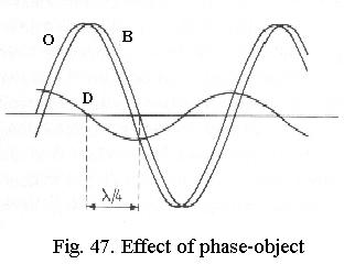
The principle of phase-contrast can be explained with the theory of diffraction described earlier. In Fig. 47 two light waves are drawn, B is the wave that passes outside the phase-object (i.e. the background illumination), O is the wave passing through the object. As drawn, it has the same amplitude as B (i.e. theres no absorption), but it is delayed (phase-difference). If we graphically plot the difference between B and O, the result is another wave D that represents the difference between the background and the object. The diffraction theory has shown what D actually is: its the diffracted light generated by the object! In the image plane, B and D interfere, which amounts to a simple addition of their graphs. Evidently this results in O, which only differs from B in phase and thus is invisible.
It can be shown that for small phase differences, D always differs in phase from B by about ¼ wavelength, the phase difference is said to be ¼ l. If D is artificially shifted by another ¼ l and then interferes with B (Fig. 48), a new wave O results, which has a smaller amplitude than B. The object is darker than the background, the invisible phase-difference has been converted to a visible amplitude difference. This effect can be further enhanced when B is attenuated (Fig. 49) so that its amplitude is the same (but of opposite value) as that of D. The wave O is then extinguished to zero, which equates to maximum dark. This line of reasoning is equally valid if D is not delayed, but advanced in phase, in that case O becomes brighter than the background instead of darker.
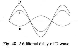
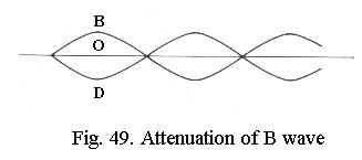
Fig. 50 shows how this is done in practice. There is an annular stop in the front focal plane of the condenser, which is imaged at infinity: parallel rays exit the condenser. The light coming from the condenser is split into two bundles by the object, the undeviated and the deviated light.
Imaging of undeviated light (left hand of Fig. 50): the undeviated light B continues its parallel path and is therefore imaged at the rear focal plane of the objective.
Imaging of deviated light (right hand of Fig. 50): the deviated light D fans out from the object and is imaged inside the eyepiece, about 160 mm above the objective.
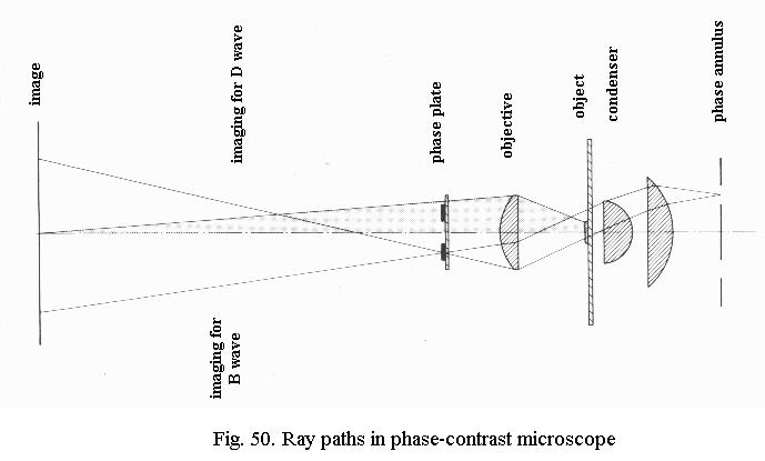
Because these two images are so widely separated, B can be tinkered with while leaving D alone. The objective has a special ring-shaped phase-plate in its rear focal plane, which corresponds in size to the image of the phase annulus in the condenser. In the phase-plate, B is given the ¼ l extra phase-shift and also attenuated (the ring in the phase-plate can be seen if you look through the objective).
Procedure is as follows: adjust illumination. With Köhler illumination you can leave the field stop open because it is not very effective anyway here. Do not forget to set the condenser iris wide open! Select correct phase annulus for objective (10x, 20x etc. as indicated on the rotating plate of the condenser), insert centering telescope, center annulus. As said earlier, the phase-contrast condenser is nothing special (actually it is mostly of the uncorrected type) and you can use any condenser and make your own phase-annulus for each objective.
Making your own: for central stop
use a washer (hardware shops) of appropriate size. You need really small
ones for low-power objectives, determine the size needed by inspecting
the phase-plate with the centering telescope and closing the condenser
iris until its just slightly larger than the inner circle of the
phase-ring. Cement the washer on a plastic disc cut to fit the filter
ring, center it while the cement is still soft. Block the hole in
the washer with black paper or paint. The condenser iris can be used to
block out the peripheral light, or you can cement a thin sheet metal disc
with a hole of appropriate size on to your home-made phase annulus. Center
also.
Limitations
Phase-contrast has its limitations.
In the first place, its only suitable for phase-objects, that is to say:
thin objects that do not cause major changes in absorption.
Surprisingly, except for some very advanced texts the literature does not point out that phase-contrast may cause a major reduction of resolution. The phase-annulus in the condenser limits the angle of admittance to less than the maximum angle the objective handles. After all, the ring in the phase-plate has to be smaller than the aperture of the objective. For the 10x, 20x and 40x objectives in a phase-contrast set, this reduction is mostly acceptable, but for some inexplicable reason the ring in the phase-plate of the 100x objective (where you want the highest resolving power) is far too small in many routine sets. Such 100x objectives do not resolve a diatom like Surirella gemma, which one can easily resolve in brightfield (without phase-contrast), even with objectives of lower NA.
When buying a phase-contrast 100x objective, inspect its aperture. If the ring of the phase-plate has a diameter less than half that of the lens, the design is not good enough.
Several manufacturers produce 100x
phase-contrast objectives with a ring corresponding to NA 0.9 approximately.
These yield both high resolution and good contrast.
Phase-contrast on the house
Ordinary objectives are also able
to yield phase-contrast, a phenomenon already known to late-Victorian microscopists,
who described the effect of an annular stop.
Such an annular stop is just like the central stop used for darkfield,
only slightly smaller so that it just passes light to illuminate the edge
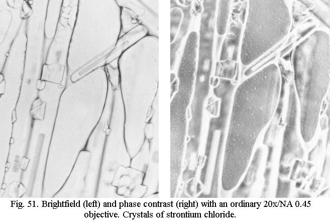
of the objective. Fig 51 shows the effect for an ordinary 20x achromatic
objective. It can be just as spectacular for a 40x objective and even a
100x objective can deliver good images if combined with a high-power darkfield
condenser of the wet type - which as we saw cannot deliver true darkfield
with an oil immersion objective of NA 1.25. The effect can be widely different
for objectives of different manufacture, however, and this is purely a
matter of experiment. Some ordinary achromats, even of vintage age, work
very well, others cant cope with this trickery.
The reason why this annular illumination
results in phase-contrast is that spherical correction of an objective
becomes less perfect at the periphery. It can be shown that this results
in abrupt phase-shifts in the wave-front at the edge of the lens. What
we exploit here is a sort of unintentional phase-plate at the edge of the
lens, of undefined phase-shift and with zero absorption. The Victorianscan be said to have failed to discover phase-contrast by a narrow margin
Polarised light
Microscopy in polarised light is
primarily an analytical method to determine various optical properties
of crystals. Thus, its a method of measurement, requiring specialist knowledge
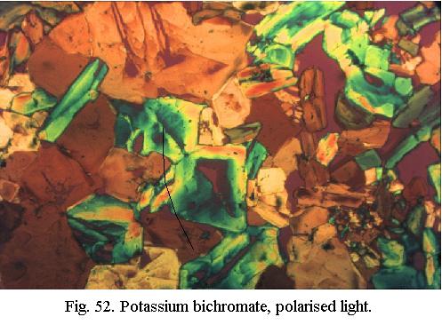
and special microscopes of considerable complexity. Simple applications
of polarised light can yield fine results, however (Fig. 52), and because
polarised light is also used for interference microscopy, heres a concise
explanation.
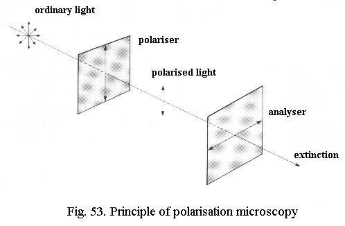
Ordinary light consists of waves oscillating in all planes perpendicular to the direction of propagation (Fig. 53). Polarizing filters extinguish all waves except those in a single plane: after leaving the polariser in Fig. 53, only the North-South wave is left. If a second filter, the analyser, with its polarizing axis in the East-West axis, is added, all light is extinguished. The two polarizing filters are said to be crossed.
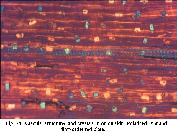
Many substances display a special optical property called birefringence: a single light ray passing through them is split into two rays, with different propagation speeds. Its as if the substance had two different refractive indices, resulting in a phase-difference between the two rays which varies with wavelength. When a birefringent substance is placed between the polariser and analyser and the two rays exiting the substance are made to interfere, a colour results that depends on the measure of the phase-shift. In one particular range of colour, very small shifts in phase lead to marked differences in hue (Fig. 54). This range lies in the red, at a wavelength called first-order red. A first-order red plate between the polariser and analyser greatly enhances the differences in colour. Birefringent objects lying in the North-South or East-West axis extinguish, which is one reason why polarizing microscopes have rotating stages.
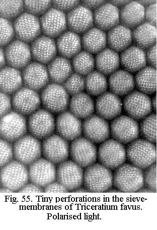
Polarised light can also be used for diatoms, making details visible that are not or barely visible in brightfield (Fig. 55). Resolution is only maximum in one direction (azimuth effect), requiring a rotating stage.
Interference microscopy
Like phase-contrast, interference
microscopy makes phase-shifts in the object visible as differences in colour
or intensity. There are many different technical principles by which interference
microscopes can be designed. In all cases, the physics is fairly complex
so that the specialist textbooks must be consulted. Unlike phase-contrast,
and like microscopy in polarised light, interference microscopy was primarily
developed as an analytical method, permitting sensitive measurement of
the optical properties of the object. The polarisation microscope is actually
a form of interference microscope.
One type of interference contrast
set, Differential Interference Contrast (DIC,
often called after its inventor Nomarski), has found wide application in
biology because its not complex in use. Such a commercially available
set, consisting of a special condenser and an attachment inserted above
the objectives, greatly enhances the visibility of phase-objects but does
not permit measurements to be made. Contrast is variable and DIC can cope
with both small phase-shifts and large ones - which a phase-contrast
set may not be able to handle. As in polarisation microscopy, there is
an azimuth effect, requiring a rotating stage.
Infinity-corrected optics
For over a century, the standard
tubelength has been 160 or 170 mm, which means that the image is formed
16 - 17 cm above the objective, inside the eyepiece. In the past two decades,
infinity-corrected optics have become increasingly used. In these systems
the image-forming rays leave the objective as parallel bundles, to form
an image at an infinite distance.
This is a rational design philosophy, derived from an old trick in polarising microscopes. Vintage polarising microscopes used rather hefty prisms as polarisers and analysers and these introduce aberrations in the image-forming rays. To avoid this, the rays were made parallel before they entered the analyser - eliminating the additional aberrations - by a negative lens, and restored to converge at the proper tubelength after they had passed through the prisms by a positive lens. This combination of a negative and a positive lens was called a Telan system and was already in use about a century ago.
The problem with a rather short tubelength of 160 mm or so is that there is little room left for additional optical components. This is why binocular tubes - which contain several large prisms - required a negative lens to compensate for the increase in tubelength, resulting in a 1.5x magnification factor. A similar situation arose with other optical components like Nomarski interference contrast.
If the objectives are corrected for infinity, the image-forming rays are parallel, as they were after passing through the negative Telan lens. You can therefore add all sorts of optical gadgets without introducing aberrations. Then a positive lens ensures convergence as in the Telan system. The latter may also be used for some additional correction (e.g. field flattening).
The switch to infinity-corrected
optics is a powerful means for manufacturers to enforce brand compliance:
the optics are only suitable for the manufacturers stands. No longer is
it possible to directly compare all sorts of lenses from different periods
and makers on a single microscope! On the other hand, if you have special
accessories to add to your microscope, infinity-corrected optics may be
advantageous.
«««««« »»»»»»