In this chapter, some of the finer - and lesser known - points of illumination will be discussed. If you just want to use the microscope for routine work, you can stick to a few rules and refer to the instructions for your microscope. If you are interested in the microscope as such, however, and especially if you wish to combine a microscope that has no built-in illumination with a stand-alone illuminator, heres some food for thought. So to begin with, heres a summary:
Summary
- the field of view should be (reasonably) evenly illuminated
- the illuminating train should be able to fully illuminate the aperture of an objective of NA = 1.0
- the light source should be focused in the object
- in critical illumination, the light bulb is the light source
- in Köhler illumination, the light source is an iris diaphragm attached to the illuminator (the field stop)
- the condenser iris is adjusted for each objective between the limits shown in Fig. 16.
Condensers
If the light source must be focused
in the object, its evidently the condenser that must do this. And as the
condenser therefore has to form an image, one may assume that this image
has to be of some reasonable quality - perhaps not as good as the image
of the object formed by the objective, but not completely junk either.
We have seen experimentally in Chapter 3 how chromatic and spherical aberration ruin the image. To what extent are the aberrations of the condenser important?
In Fig. 39 the operation of the condenser is illustrated. Rays from the light source are drawn continuous, dotted lines show the image formation of the condenser iris. This image should be located at an infinite distance behind the condenser. The design of the condenser should, therefore, be such that the condenser iris is located in its front focal plane. The condenser delivers a bundle of light up to its maximum NA (0.95 dry, higher only if used wet) into the objective. Effective condenser NA is adjusted by stopping down with the condenser iris. If only a small portion of the condenser is used, spherical and chromatic aberration are greatly reduced and the first conclusion, therefore, is that up to about a 20x, NA 0.45 objective we need not worry.
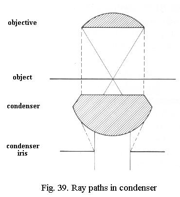
If we talk about correction for spherical aberration, its necessary to refer to a complicating factor. Any lens can form an image of an object placed at any distance, although the position of these images will be very different. The design rule for spherical correction is that good correction can only be obtained for exactly specified locations of the object (in front of the lens) and its image at other exactly specified locations behind the lens. For other locations, spherical aberration will still be present. These locations for which spherical correction has been optimized are called the aplanatic points.
Manufacturers happen to have marketed two different types of condensers, unfortunately without specifically sayingwhich type it is by engraving it on the condenser. The first is corrected for infinity: its so designed that spherical correction is best if the light source is at an infinite distance from the condenser. One (front) aplanatic point is thus at infinity, the other lies at the natural (rear) focus of the condenser. Simple (uncorrected) condensers sometimes (and quite erroneously) called Abbe-type condensers of vintage microscopes - but also much later - fall in this category.
The second is corrected for a much smaller distance of the light source, typically 35 cm or so. This is not unreasonable because the illuminator will be placed on the bench, or is built into the microscope. The front aplanatic point will then be at about 35 cm. Typical examples are found among modern highly corrected condensers.
Even dealers tend to acquire a hazy or even chastising look if you ask them whether their condensers are designed for infinity (possibly because they fear you want to have a warranty for that period), but fortunately you can find out for yourself:
Experiment:
Focus with a 10x objective on a
slide. Do not use the low power setting
of the condenser if it has one. Use the flat mirror (if the microscope
does not have a mirror use a pocket mirror) to catch an image of some object
outside the room, e.g. trees. If you can focus this easily by racking the
condenser almost completely up, the condenser is designed for infinity.
If you cant, its front aplanatic point is closer and you can find out
where by holding a pencil at some distance away from the mirror and moving
it forwards and backwards until its image in the microscope is sharpest.
Critical illumination
This form of illumination is typically
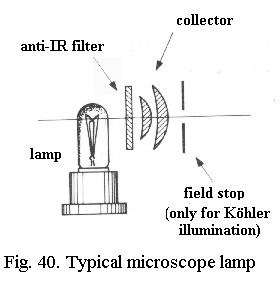
intended for a condenser corrected for infinity. The illuminating train
(Fig. 40) starts with a light bulb and this is followed by a lens system
(one lens in the simplest case, two or three in other designs) which projects
the filament of the lamp at infinity. This lens system is called the collector.
The light thus leaves the lamp as a parallel bundle. The condenser is corrected
for infinity, the lamp filament now appears to lie in its front aplanatic
point and is focused in the object with the lowest spherical aberration
the condenser can yield.
The disadvantage is that the filament
is seen in the object, so the field of view is not evenly illuminated.
For that reason the light bulb, or one of the collector lenses, is given
a lightly frosted surface. Another shortcoming is that the slide is illuminated
by a strongly convergent cone of light which causes some glare, slightly
reducing contrast.
Köhler illumination
In this case, the filament of thelamp is focused by the collector so that it is sharply imaged in
the front focal plane of the condenser. The filament is thus projected
as an image at an infinite distance behind the condenser. That implies
that the slide is now illuminated by a parallel bundle of light, reducing
glare. Also, because the image of the filament now lies at infinity, it
is no longer seen in the object and illumination becomes more even.
In addition, a Köhler lamp has its own iris diaphragm (Fig. 40). If this is situated at the location of the front aplanatic point of the condenser, it will be sharply focused in the object. The portion of the object illuminated can now be restricted only to what you actually see in the microscope (the field of view), reducing glare. That is why the lamp iris is called the field stop. It is evident, however, that the field stop is not at infinity but close to the condenser. This means that the condenser should be corrected for a shorter distance (conventionally about 35 cm or so) than infinity.
You can use an infinity-corrected condenser in this situation if you combine it with a correction lens. This works just like reading-glasses for people, the lens should have a focal distance of about 35 cm (+ 3 diopter) and is placed in the filter ring. The vintage microscope of Fig. 9 has a very good aplanatic condenser but I can only use it for Köhler illumination if I combine it with a correction lens, otherwise the condenser performs very poorly.
Things are rarely ideal in optics,
and although Köhler illumination is supposed to give a perfectly evenly
illuminated field of view, this is not always the case. Therefore, the
light bulb or a collector lens is mostly lightly frosted in this case also.
What price condenser?
All manufacturers produce the simple
uncorrected condenser, but many also offer more highly corrected types.
An uncorrected condenser is cheap, an aplanatic one may cost about double,
an achromatic-aplanatic one is about twice as expensive again. In view
of the difference, one may wonder whether the benefits balance the cost?
Much has been written about this and mostly the conclusion amounted to something like the expensive ones are better When I first seriously tackled microscopy, I ran into a major problem which I had to solve myself because the literature did not discuss it and dealers could not help. Since then, I have found only one publication (Teach yourself microscopy by W.G. Hartley, The English Universities Press, 1962 and possibly later editions) that exactly described the problem I had run into and clearly identified the cause.
Experiment:
At low power (10x or 20x objective)
set up Köhler illumination according to the instructions in your manual
or as given at the end of this chapter. A slide with diatoms is excellent
for this, focus on the object. Check the aperture to verify that about
80% of the objective is filled with light. Close down the field stop (which
should be sharply focused in the field of view) until you just see it appear
at the edge of the field of view. A nice Köhler image should be seen.
Switch to 100x oil immersion, refocus on the object. Use the condenser dry, open up the condenser iris fully. Check that about 80% of the aperture is filled with light. While looking at the object, close down the field stop until you see its edge.
If closing down the field stop causes obvious changes in the image, notably a marked reduction of resolution, check the aperture. In that case, closing down of the field stop (juggle with its setting) results in restriction of the illuminated portion of the aperture and you have a problem: severe spherical aberration of the condenser makes the field stop act like an aperture stop.
In this case, you will have to set the field stop much wider open than necessary. Strict Köhler illumination, which aims at reducing glare by limiting the illuminated portion of the object, cannot be attained because resolution will be ruined. The alternative to leaving the field stop open is to use critical illumination, which also works with a poor condenser.
An aplanatic condenser will still sufficiently fill the aperture of a 100x oil immersion with light if the field stop is small - just large enough to be seen at the edge. So Köhler illumination at high NA does not run into problems then. The edge of the field stop will still show a colour fringe, though. Focus the condenser until the inner fringe is blueish and open up the field stop slightly so that the colour fringe is outside the field of view. An aplanatic-achromatic condenser minimizes this colour fringe.
The conclusions are clear-cut:
- An uncorrected condenser permits strict Köhler illumination up to NA 0.45 or 0.6. (some uncorrected condensers are more uncorrected than others). At higher NA, the field stop must be larger than optimum or critical illumination must be used.
- An aplanatic condenser will permit strict Köhler illumination at high NA. Open up the field stop just a bit more to avoid a false colour-tinge in the image (colour photomicrography!).
- An aplanatic-achromatic condenser minimizes the false colour-tinge.
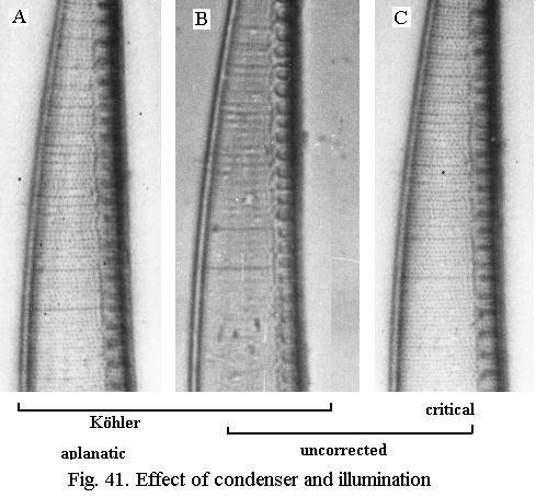
- Fig. 41a: Köhler illumination, aplanatic condenser.
- Fig. 41b: same set-up, aplanatic condenser exchanged for an uncorrected type. The dots are no longer resolved.
- Fig. 41c: same uncorrected condenser as in Fig. 41b but now with critical illumination. Theres a bit more glare than in Fig. 41a and the field of view is not perfectly evenly illuminated, but the dots are resolved.
General recipe for Köhler illumination:
- the lamp filament is focused (adjusting the lamp collector) sharply in the front focal plane of the condenser (where the condenser iris lies). This can be checked with a piece of white paper.
- the filaments image should fill the entire lower opening of the condenser. Check also that it is nicely centered on the condenser opening, if necessary adjust bulb centering screws.
- focus microscope on slide
- reduce field stop to small size, focus condenser for sharpest field stop image
- open field stop until field of view is illuminated, center field stop if required
- set condenser iris for good image
Ray-paths
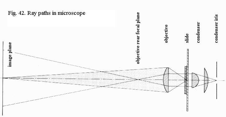
Fig. 42 shows the ray-paths for
the illuminating and image-forming rays in the microscope. This is especially
helpful for understanding phase-contrast.
The object is situated in the front aplanatic point of the objective and imaged at the tubelength distance (160 mm) in the eyepiece. The light source is either focused in the object (critical illumination) and imaged like the latter, or focused in the front focal plane of the condenser (Köhler illumination). In this case, parallel light illuminates the object and is focused in the rear focal plane of the objective. The field stop (= light source) is imaged like in critical illumination. The condenser iris is in the front focal plane of the condenser and is imaged like the filament in Köhler illumination, in the rear focal plane of the objective.
«««« »»»»