USE of the LOGITECH QUICKCAM PRO 9000
for photomicrography
History of a
near-failure, or a semi-success
PART III
WALTER
DIONI
CANCÚN, MÉXICO
INTRODUCTION
In
the previous article I described the behavior of my new camera using normal
lighting in bright field. I think it should be clear that in
this configuration, I find the Logitech extremely useful, although it has
behaviors that a professional microscopist (and some senior amateurs) might
object to.
Like many digital cameras it is sensitive to deficiencies in the illumination such as slight unevenness of intensity across the field which the eye can often tolerate. Setting the microscope's lighting, whether Köhler or critical (for my stand critical) to the optimum before undertaking photography is essential. Despite the limitations of my own microscope's lighting, it
still gives me very acceptable documents from an amateurs point of view.
These include Oblique Illumination, Darkfield Illumination, Rheinberg Illumination, Polarized illumination, and the Reflected Illumination at low magnification (also called Incident Light).
In consultations I made with some
colleagues before installing the camera, I was told that some of their Microcular Cameras (ultimately webcams
installed with relay sensor lenses replacing the eyepiece of the microscope, so
that the image covers the total field sensor) showed some difficulty to accept the
application of some of these techniques, or definitely did not accept them. So
my first task for adapting the camera for use in afocal technique, was to test
its capabilities. First results were disappointing. But a few tricks got some
acceptable results.
An introduction to the topic may be
http://www.microscopy-uk.org.uk/mag/artdec03/wdonion2.html
In what follows, I will try to
confine myself to the special features which I found necessary to obtain the
best results with the Logitech. Also I will try to limit the images to the
description of the result obtained with this camera.
1)
Before
anything else, Köhler or Critical lighting must be installed, as usual.
2) I had not previously insisted on an
important detail: a diaphragm field
should be used in the lamp of the microscope. If, as with most budget microscopes, the lamp does not have a field
iris diaphragm, the enthusiast who wants to use the Logitech, if did it not
already, must read now this MICSCAPE articles and apply its recommendations
Ian Walker : http://www.microscopy-uk.org.uk/mag/artsep02/toptips11.html
Not
to use a field diaphragm will inevitably lead to an excess of diffuse light
reaching the sensor, producing glare, contrast and colors.
3) Install the camera (if not already
done so) and verify that you are working in the default configuration. Not to do so
will result in major defects (Irregular backgrounds, Central spots of bright light,
Aberrant contrast or color, etc.). Once the white balance is set, disable changes
to this
option. Immediately disable the auto-focus. The image will most likely be too
light, but this will be fixed easily by slightly decreasing lighting and contrast.
Install filters, diaphragms, or whatever you wish to use, and properly adjust
light, contrast and color intensity. Carefully manipulate the camera and the
microscope commands to optimize the image. Remember that, unlike the
traditional technique, and in contrast to the field diaphragm, the aperture
diaphragm must be correctly adjusted to give the optimal image. Later,
if deemed necessary, a small adjustment of the aperture iris to improve resolution
can be made.
OBLIQUE ILLUMINATION
http://www.schwaben.de/home/mathias/emikro/kontrast1.html
Dieter
Gerlach: Das Lichtmikroskop, Thieme (Stuttgart), 1976
http://www.microscopy-uk.org.uk/mag/artoct03/wdoblique.html
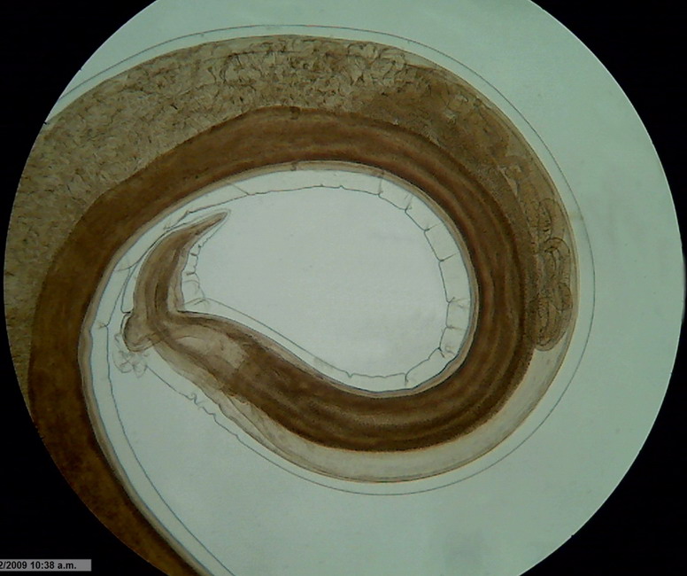
Fig.
1 - Logitech - Brightfield X10 zoom to 1400 px - flat illumination
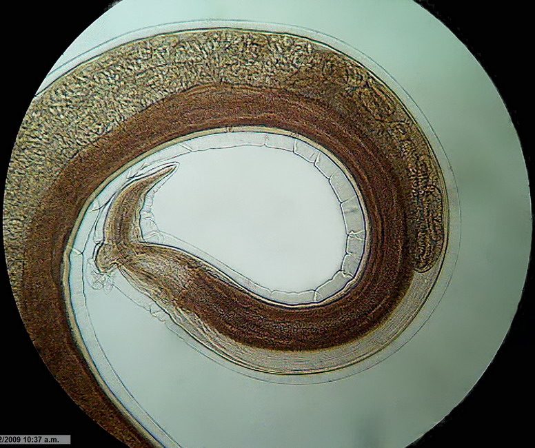
Fig.
2 - Logitech Brightfield x 10 idem Gerlach Fork
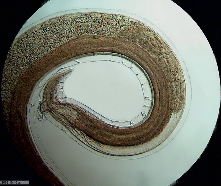
Fig. 3 - Logitech Brightfield x 10 idem Mathias
Arrow
(also
see the image in the polarized light seccion)
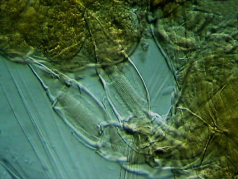
Fig.4
The fifth pair of legs of a female copepod. Mounted on GAF (see http://www.microscopy-uk.org.uk/mag/artmay03/wdpart3c.html)
In
the upper right corner is the full egg sac. Reduced clipping of 800x600
px from the original picture. The stop used was a 15 mm diameter dark disk,
decentred tilting the filter holder. x40
objective.
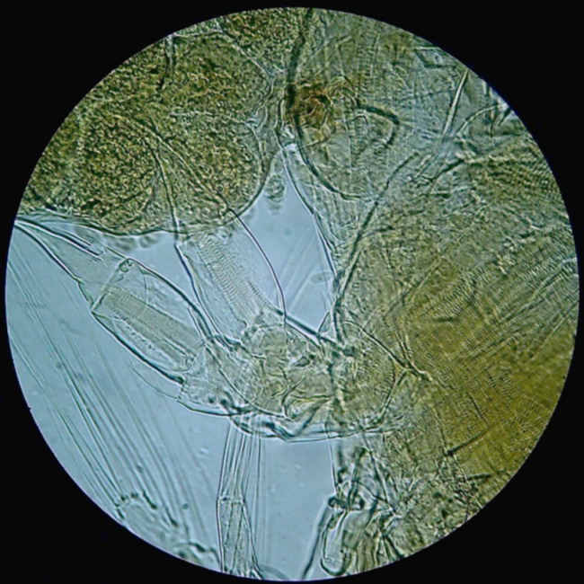
Figure 5 - This is the "flat" version in Brigthfield
Not
all subjects respond favorably to this technique. Obviously subjects with
moderate relief and well-outlined structure are
ideal. Diatoms, micro-crustaceans, micro-arthropods in general, spicules,
fibers, or hair, provide opportunities to experiment with this
technique. Dry mounts are a good observation medium. Any
other media
will interact with the subject according to their refraction and only
experimentation will show their real behavior.
http://www.archive.org/index.php
But with the Logitech I can
achieve a good approximation, provided
that the central opaque disk used has enough density. To get the proper effect I needed
to
superimpose up to 4 and sometimes 5 central black stops, printed with my inkjet
printer. But
this, in addition to being tedious, it also increases the opacity of the transparent
peripheral ring. So,
now, I'm preparing my stops by cutting the central disc from a fully opaque
material, and pasting it with nail polish over a relatively rigid disk of the most
transparent plastic available. All
my stops are made today that way.
But even using a suitable
stop, with some subjects the gamma value of the photomicrograph should be
decreased a little, for the black background to look uniform.
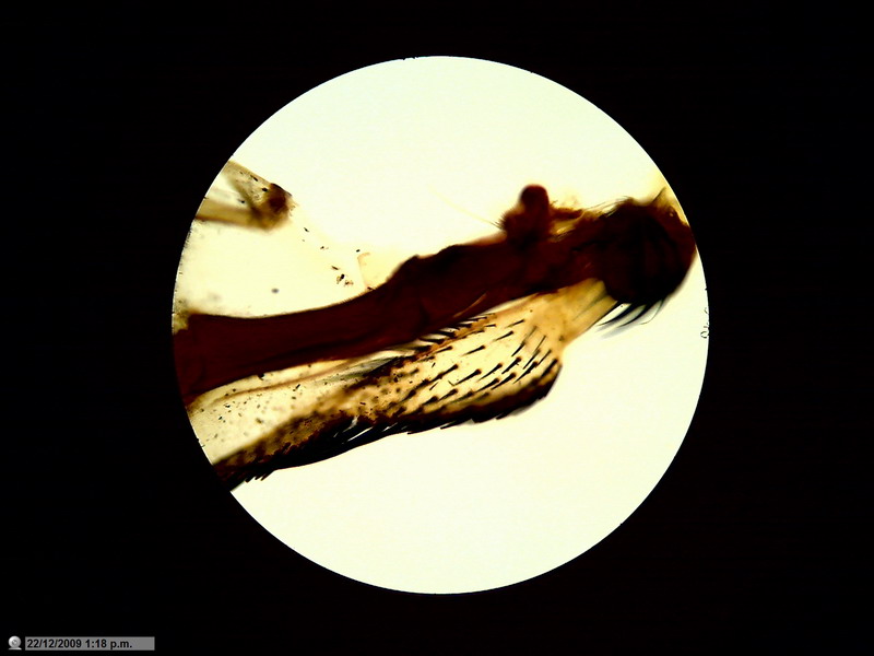
Fig. 6 - articulation, fly wing, brightfield, obj. 4x
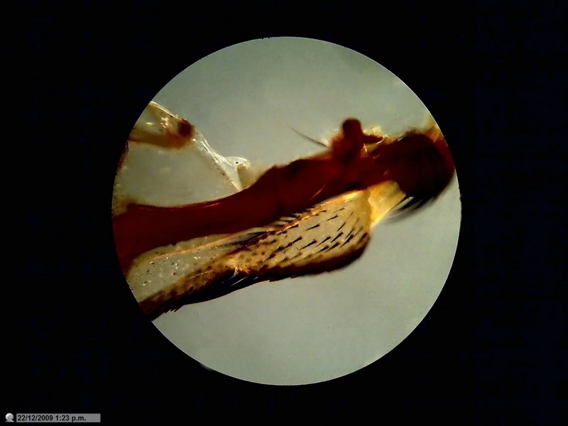
Fig. 7 - Idem. Neutral background. Mathias
arrow . x 4 one pass through NetImage
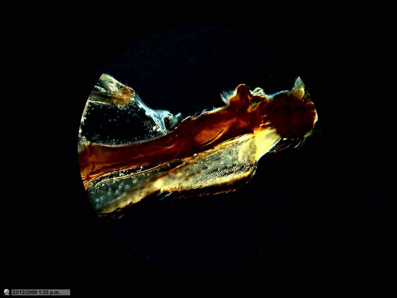
Fig. 8 Idem, Mathias arrow - 4 x - Dark background.
One pass through NetImage, gamma control
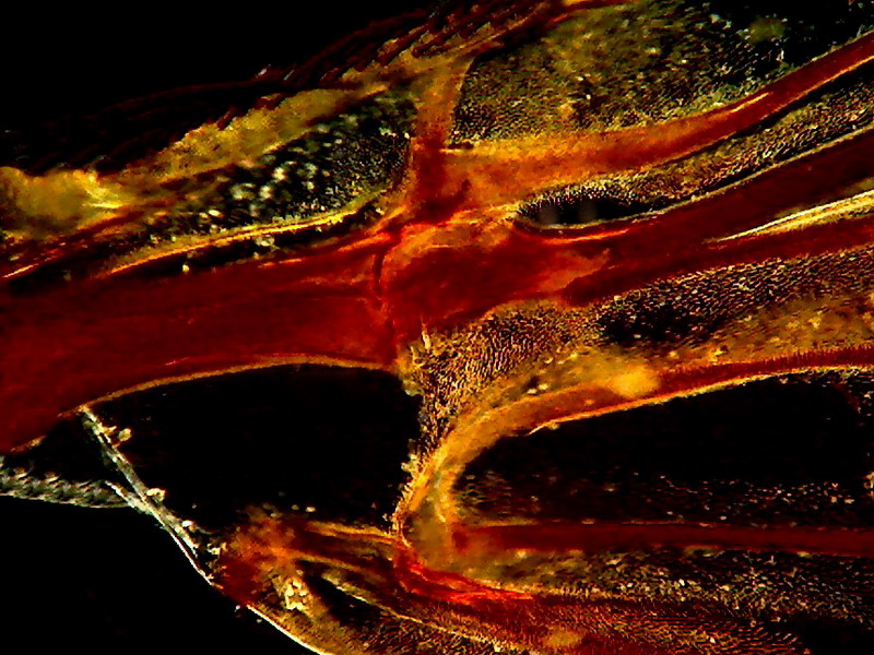
Fig. 9 Fly wing - 12 mm stop - x 10 - without
post-processing, except a moderate background cleanup
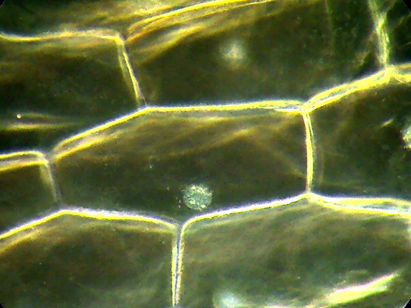
Fig. 10. A classic subject x 40, 15 mm stop. One pass through NetImage. The focused nucleus shows
its 3 nucleoles.
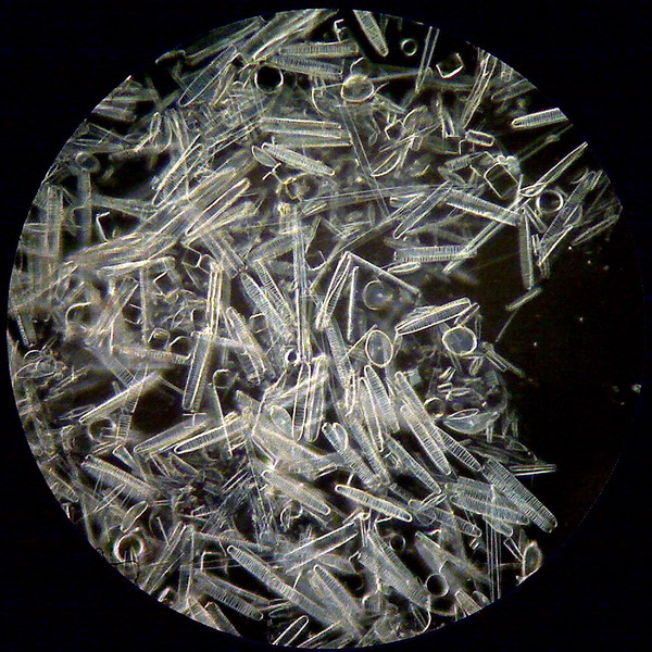
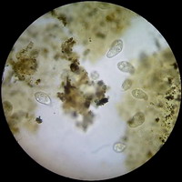
Figure 11 - Diatoms with the 40x objective - A group
at the edge of a preparation kindly donated by Dominique Voisin - 15 mm very dense stop. Without any postprocessing
but size reduction.
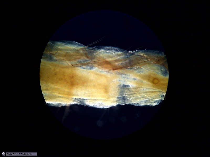
Fig. 12 - Body of a mosquito larva mounted in
PVA-G. "Polarized Darkfield"
As
well as allowing "Brightfield",
almost similar to that obtained removing any filters, and stops, a good variety
of intermediate densities and even "dark field" are produced by
the crossed polarizers. For some subjects, with a slight displacement of the
condenser filter holder, interesting highlight effects can be achieved. Of course, polarization affects only the
background. The subject is only illuminated by unpolarized light, as in
the other dark field techniques.
RHEINBERG LIGHTING
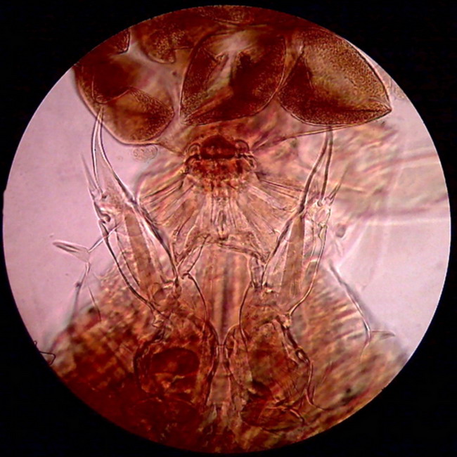
Figure
13 - The picture above shows the two hind legs of a female copepod, the point
of attachment of the bag of eggs, and the first part of this bag. Eggs are
deformed due to dehydration suffered when mounting the piece. The subject
is greenish, as was shown before in bright field images and oblique
illumination, but with the use of a Rheinberg filter with blue center and red
ring, it appears to have been colored with carmine or eosin. The
center was not sufficiently dense, but the effect is still
good.
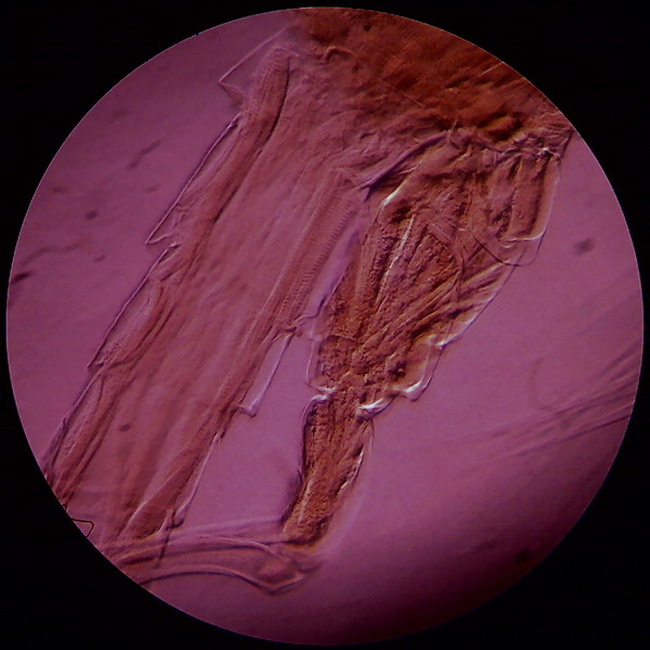
Fig
14 - the same previous filter, slightly eccentric because of a slight
displacement of the filter holder, highlights the relief features of the
exoskeleton and muscles in the fifth leg and the beginning of the queue of a
male copepod. In this case the price of the relief is the strong red dominant on
the background
POLARIZED LIGHT
There are many articles in MICSCAPE library that
can serve as an introduction, or efficient guide, to this so appealing
technique. Look under
Techniques - lighting and light sources
French readers can also find information more
than enough in the Forum Mikroscopia
and its Microscopies magazine.
Popular Science: Oct. 1934 pg 69.
http://blog.modernmechanix.com/2007/05/15/polarized-light-experiments/
One
Way With Simple Polarizing Units and Imitate Feats Performed
Popular Science Octubre 1938: pag 200.
http://www.popsci.com/archive-viewer?id=hiYDAAAAMBAJ&pg=200&query=polirized+light
To prepare crystals to observe or
photograph in polarized light, unpretentious scientific nor mineralogical, this
article has enough information: Pavlis: http://www.microscopy-uk.org.uk/mag/indexmag.html
Fig.
15 - aqueous solution, dried on the slide of potassium dichromate. Completely crossed polars plus Oblique
illumination (Mathias wedge). Reduced from 1000x1000px. This is my first
crystallization. The capricious forms adopted by crystals often suggest
landscapes. My imagination dictates me "Tropical forest" as a name
for this image. The suggestion and description of this mixed lighting
(polarized and oblique) technique can be read in the article of Paul James:
and also in the more complex Ian Walker article
http://www.microscopy-uk.org.uk/mag/artjan05/iwsworlds.html
Fig.
16. The same field of view, but without the oblique illumination stop
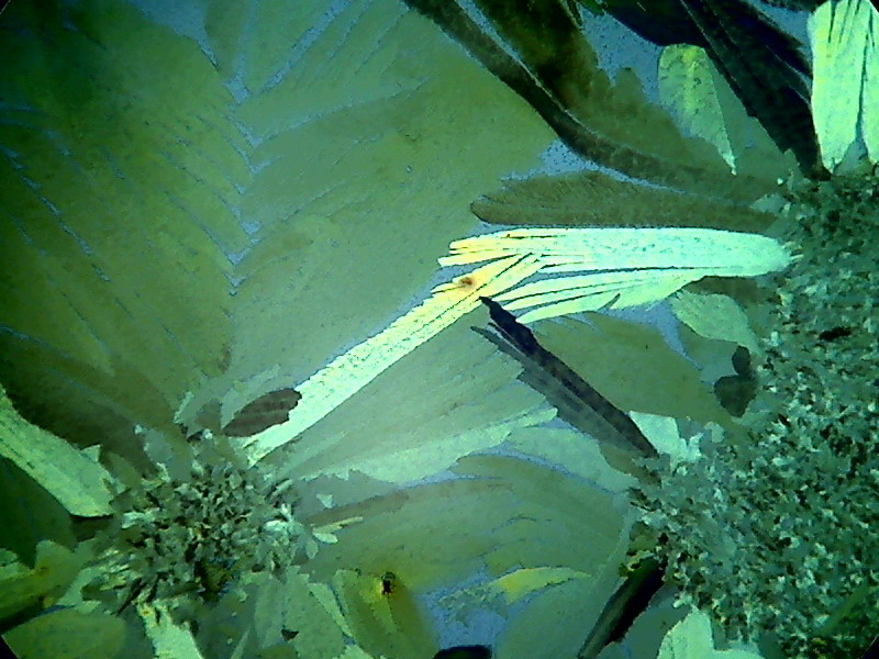
Fig. 17. The same field of view: A rotation of only a
few millimeters
INCIDENT illumination REFLECTED
Light
I used this method with the Logitech,
but soon I discovered that for some subjects when working near the window of my
lab, the daylight was enough for the Logitech to capture the subject without
having to employ any reflector.
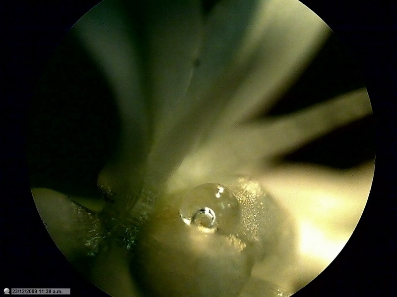
Fig.
20 - A drop of water, encompassing a drop of air, over the ovary of a flower of
"Allium sp." Lighting: a handheld flashlight, obj. 4 x. Direct light without
diffusers
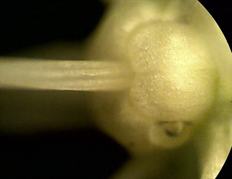
Fig.
21: Ovary superior, flower of "Allium sp", x 4, Lighting: a cylinder
of architect paper, handheld flashlight with two1.5 V batteries. Single picture.
Of course as the subject was appropriate, a 'Stack' for CombineZ could have been attempted.
There are several works on
the Internet
which propose small homemade instruments equipped with LED's, fed with
batteries and controlled with potentiometers, that can work with efficiency for
reflected light.
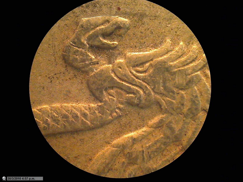
Fig
22 - The above image is a shot with the 4x objective, of the surface of a
Mexican coin in common use. The
coin has a diameter of two centimeters. The area covered is about 4 mm in
diameter and shows the head of an eagle seizing a snake.
LIVE
SUBJECT PHOTOMICROGRAPHY
AND VIDEO RECORDING
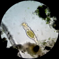
Fig. 23. Click on the photo to view the video
As always before start working, all
the routine of initiation as explained at the beginning should be applied, preparing
good, clean and thin wet mounts, or using any extra-thin wet cameras as described in
STILL
PICTURES OF MOVING SUBJECTS
With the larger sizes
(from 1.3 Mpx onwards) still images of mobile subjects take on average a second
to be captured, so notstill images of the
majority of moving living things may be taken.
If for still images it
s surmountable,
as we saw earlier, it is really limiting when it comes to video.
The first logical format, starting
with the largest, is the native 2 Mpx. However a single 1600 x 1200 image is
partly displayed out of my 15-inch screen, set to 1440 x 900 px, even if, as in
this case, just use the sensor
partially. Therefore, while it is a most useful picture format for still subjects,
its not suitable for videos.
They do not claim technical
qualities of any kind. I simply
use them to show, with a fast-moving material, the capture sizes and speeds
collected.

Sequence
of 3 pictures 200x200 (fig 24-25-26)
Sequence
of 2 pictures Fig.
27 28
Fig
29
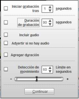
where
you can select the desired parameters. With the "Recording duration"
command off, videos can reach a very long duration. If enabled, you can set a
specified time, after which the recording will stop automatically.
IN SUMMARY
My intention, buying the Logitech,
was to have a 2 Mpx camera, to achieve a good electronic resolution of my
microscope field of view with all my objectives, including in particular the
4x.
From this point of view,
my adventure was a failure. When
I started it I did not realize that, to achieve this result in afocal geometry,
I had to change or remove the camera lens, and change the eyepiece of the
microscope for a good brand Super Wide Field (SWF) eyepiece, with 20 to 23 mm
diameter of its Field of View, and, preferably, with high eyerelief.
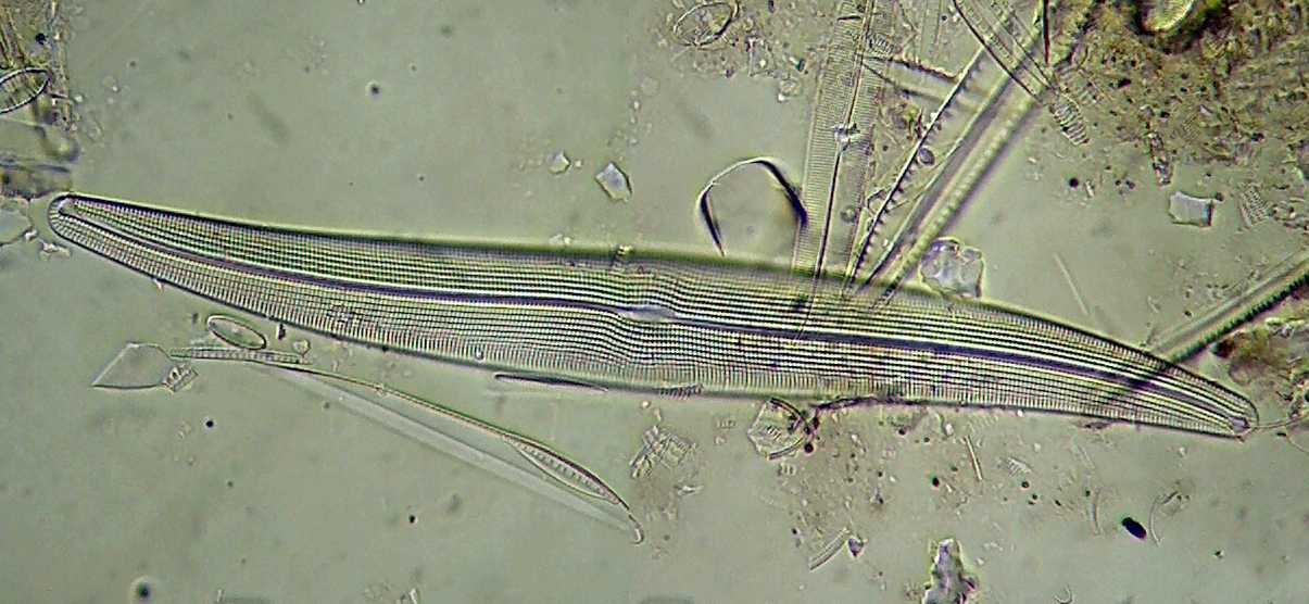
Fig. 30 Gyrosygma sp. -
100xOI Objective. From a preparation given to the author by Dominique Voisin.